System for automatically acquiring optically coded information, illuminator for said system and method for aligning with each other optical components of the system

a technology of automatic acquisition and optical encoded information, applied in the direction of instruments, lighting and heating equipment, sensors, etc., can solve the problems of reducing the efficiency of the system, wasting the majority of the light emitted, and reducing the exposure time, so as to maximise the light intensity of the image and optimize the alignment

Active Publication Date: 2012-11-13
DATALOGIC AUTOMATION
View PDF12 Cites 0 Cited by
  • Summary
  • Abstract
  • Description
  • Claims
  • Application Information

AI Technical Summary

Benefits of technology

[0016]Owing to the invention it is possible to obtain an optimal alignment between the line of view of the optical sensor and the light beam emitted by the light source so as to maximise the light intensity of the image that is formed on the optical sensor.

Problems solved by technology

In linear acquisition systems known from the state of the art the main problem is to generate an extremely thin and concentrated light stripe so as to maximise the intensity of the signal received by the sensor, reducing the exposure time and permitting the image of the support to be “frozen” even when it is moving with respect to the acquisition system at relatively high speeds.
On the other hand, the thinner the light stripe, the more difficult is the operation of mutual alignment between the illuminator and sensor; even a slight misalignment between the sensor and the illuminator means causes the field of view of the sensor to fall outside the peak of intensity of the light stripe, reducing the efficiency of the system and wasting most of the light emitted.
This problem is addressed by the systems of the prior art in an unsatisfactory manner.
Further, the described solution discloses an illuminator that is constructed as a single block, that extends over the entire width of the field of view of the sensor, so even a small angular misalignment of the sensor, due to the length, results in a loss of efficiency at the ends of the sensor, which may even be significant, having a peak of intensity at only one point of the sensor and possibly null intensity at the ends.
In addition, the disclosed system is not coaxial, so in fact the overlap between illumination and field of view of the sensor is obtained only in a zone near the second focus of the ellipse; the ability to illuminate and identify information on supports arranged at different distances from the sensor is greatly diminished thereby making ineffective any technique for increasing the depth of focus of the objective lens, such as, for example, the automatic focusing techniques mentioned above.
Simply replacing these sources inside the previously disclosed device makes it impossible to be carried out because the mechanical tolerances alone are not able to ensure the required alignment, and the greater concentration of light would further reduce the reading depth of the system.
The compactness of the sources enables a very thin stripe to be generated, the coplanarity with the field of view of the sensor significantly extends the reading depth of the system, but the problem of alignment is increased.
This is a costly and complicated system, that attempts to compensate for each orientation error of the source with rectilinear and rotation movements on different axes; as each subsequent adjustment around an axis different from the first axis influences the preceding adjustment, not necessarily in the sense of an improvement, the risk is to be forced to perform an interactive procedure in which, once the illuminator has been adjusted on an axis, it is necessary to go back and correct the calibration on the preceding axis.

Method used


Image

  • System for automatically acquiring optically coded information, illuminator for said system and method for aligning with each other optical components of the system
  • System for automatically acquiring optically coded information, illuminator for said system and method for aligning with each other optical components of the system
  • System for automatically acquiring optically coded information, illuminator for said system and method for aligning with each other optical components of the system

Examples


Embodiment Construction

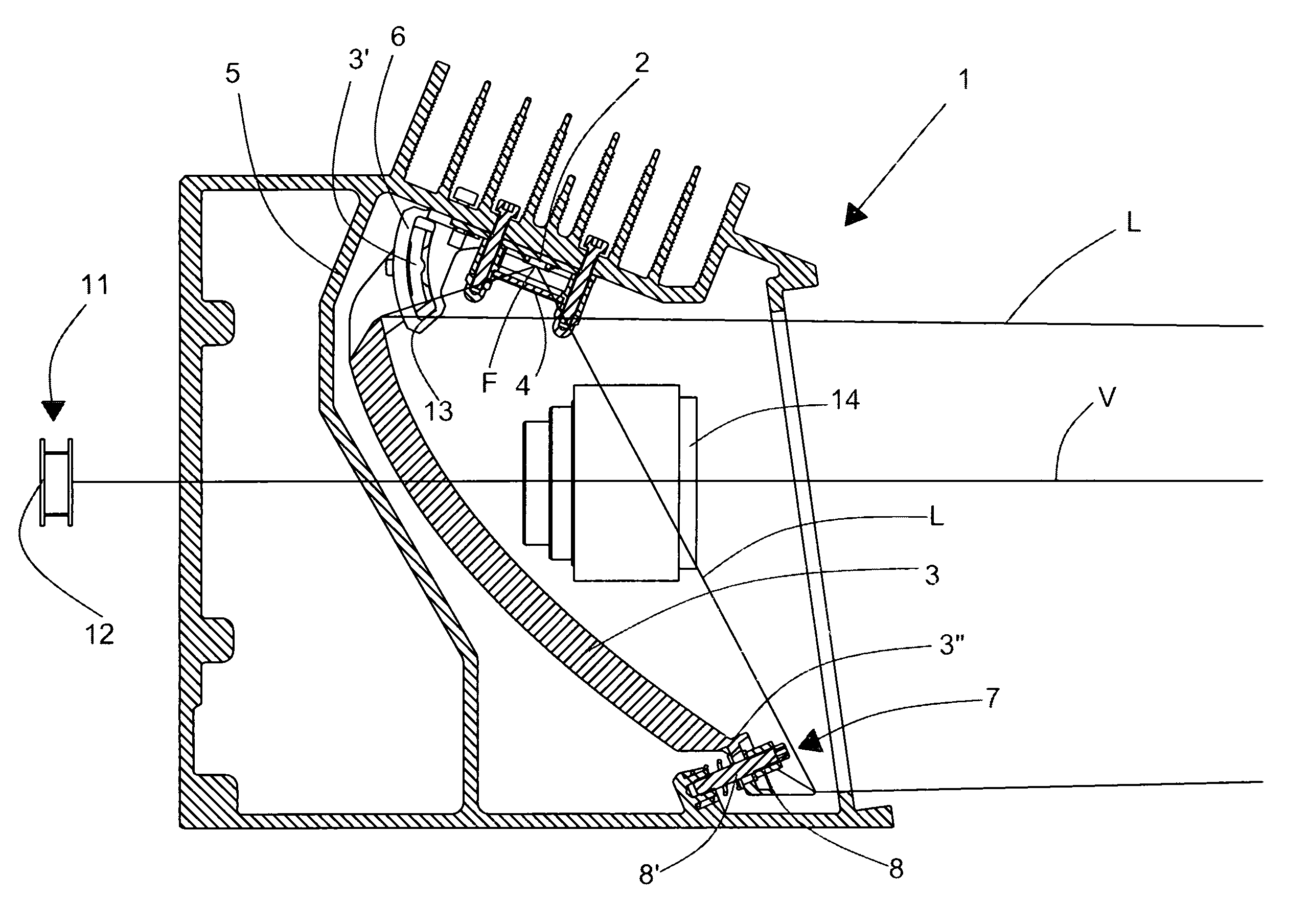
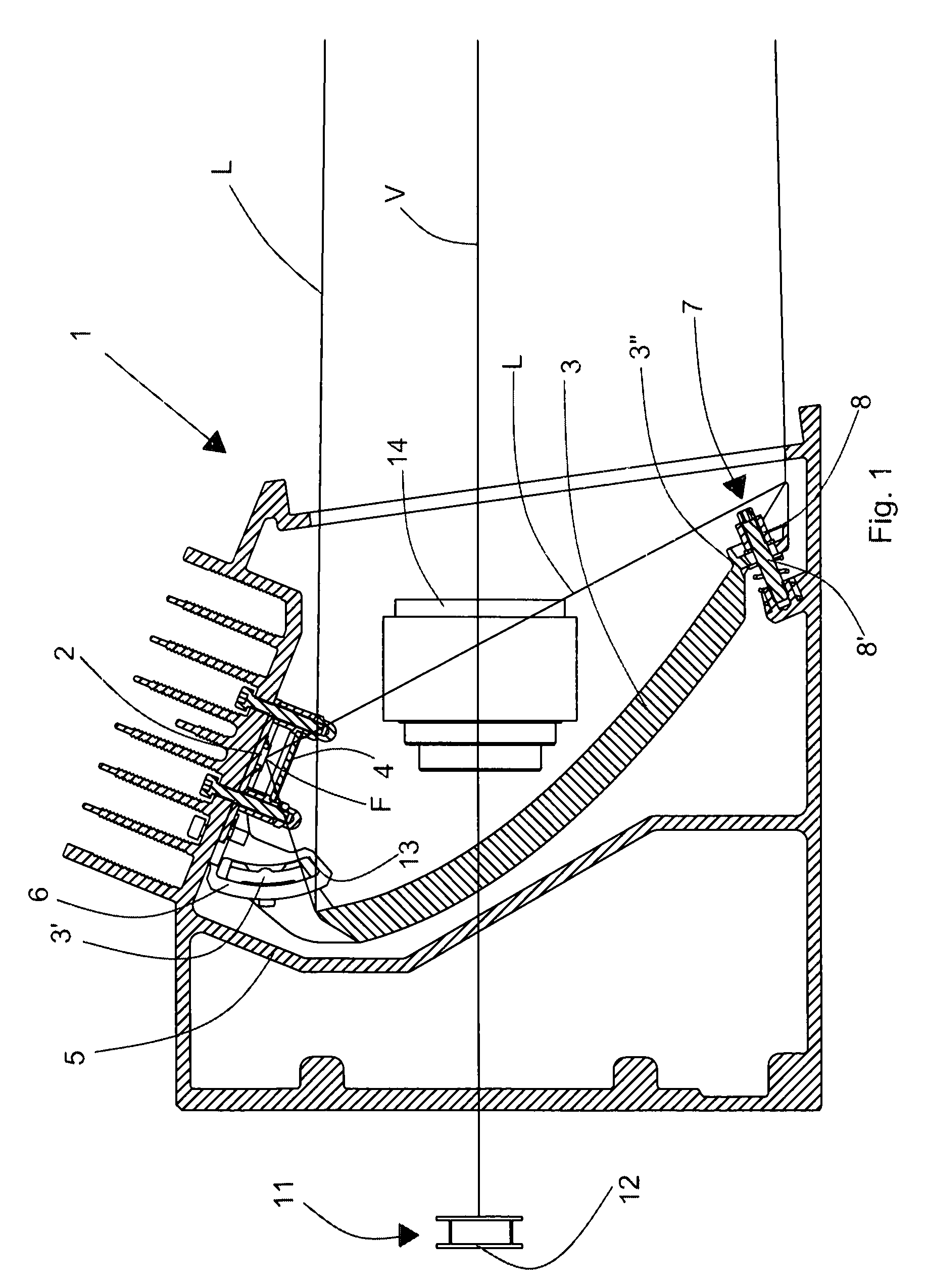
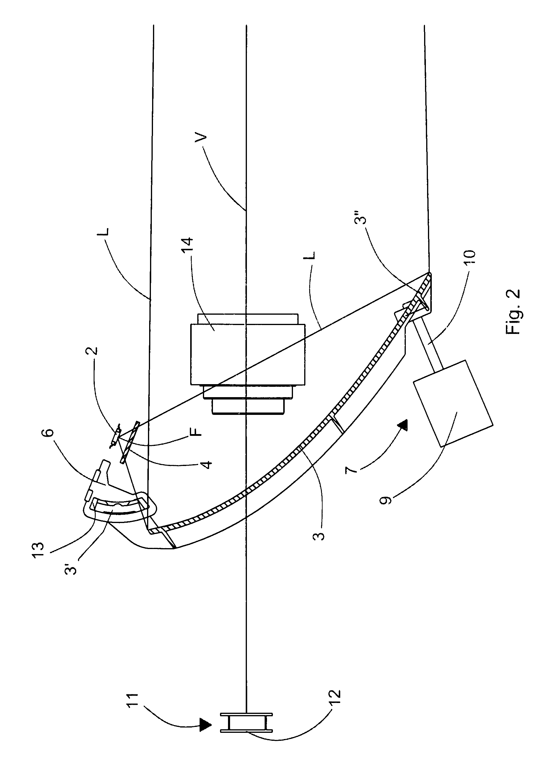
[0030]With reference to FIG. 1 an illuminating device according to the invention comprises at least one illuminating element 1 provided with a linear light source 2 consisting, for example, of an array of solid-state emitters, for example high-power LEDs, and extending along a first direction, a reflecting optical element 3 that receives a light beam L emitted by the light source 2 and reflects it towards a reading zone where the light is intended to illuminate an optical code impressed on an object, that has to be read by an image-acquiring device 11, for example a television camera, or camera, that comprises an objective lens 14 that forms an image of the optical code and an optical sensor 12, for example a linear sensor, that is arranged at the image forming plane, or image plane, inside said image-acquiring device 11. The reflecting optical element 3 is shaped so as to have at least one first linear focus F in an area around which the light source 2 is arranged. Between the ligh...


PUM


Abstract

An illuminating device for a system for automatically acquiring optically encoded information includes at least one illuminating element, the at least one illuminating element including at least one linear light source extending along a first direction, at least one reflecting optical element associated with the at least one linear light source and suitable for reflecting a light beam emitted by the at least one light source, the optical element having at least one first focus, the linear light source being arranged within an area surrounding the first focus, the illuminating device further includes rotating means suitable for rotating the at least one reflecting optical element with respect to the at least one first focus, with a rotation center arranged within a further area surrounding the at least one first focus.

Description

FIELD OF THE INVENTION[0001]The present invention relates to a system for automatically acquiring optically encoded information, in particular a system for acquiring images of optical codes, an illuminator for said system and a method for the reciprocal alignment of the optical components of said system.BACKGROUND[0002]In the continuation of the present description and in the subsequent claims, the expression “optical code” is used to indicate any graphic representation having the function of storing encoded information by means of suitable combinations of elements with a preset shape, for example square, rectangular or hexagonal, of a dark colour (normally black) separated by clear elements (spaces, normally white), such as barcodes, stacked codes, i.e. codes with several sequences of superimposed bars and two-dimensional codes in general, colour codes, etc, and alphanumeric characters. The term “optical code” comprises graphic representations that are detectable not only in the fi...

Claims


Application Information

Patent Timeline
Patent Type & Authority Patents(United States)
IPC IPC(8): G06K7/10
CPCG06K7/10732G06K7/10811
Inventor VONMETZ, KURTGUASTADINI, FABRIZIOPELLEGRINO, LUIGIFIORINI, DANIELE
Owner DATALOGIC AUTOMATION
Why Eureka
Try Eureka