Eureka AIR delivers breakthrough ideas for toughest innovation challenges, trusted by R&D personnel around the world.

Wavelength detector, wavelength stabilization laser device, and image display device

a wavelength stabilization laser and wavelength detection technology, applied in the direction of optical radiation measurement, interferometric spectrometry, instruments, etc., can solve the problems of more likely changes in the mode of laser light, device complexity, and error in wavelength detection of laser light, so as to achieve high color reproducibility

Inactive Publication Date: 2009-12-08
PANASONIC CORP
View PDF4 Cites 0 Cited by
  • Summary
  • Abstract
  • Description
  • Claims
  • Application Information

AI Technical Summary

Benefits of technology

[0017]Therefore, an object of the present invention is to provide a wavelength detector capable of distinguishing between the changes of a transverse mode and of a longitudinal mode of a laser light and thus detecting the change of the wavelength of the laser light with high accuracy, a wavelength stabilization laser device using the wavelength detector, and an image display device using the laser light generated by the wavelength stabilization laser device as a light source.
[0020]It is preferable that the two photodetectors measure diffraction angles of the ±n-order diffracted lights with respect to the 0-order diffracted light by moving to positions for maximizing the light intensities of the ±n-order diffracted lights. In this case, the wavelength detector detects the change of the wavelength of the laser light based on an average angle of the diffraction angles of the ±n-order diffracted lights measured by the two photodetectors.
[0023]The wavelength detector may further include lenses, in front of the two photodetectors, for increasing beam diameters of the ±n-order diffracted lights.
[0029]Further, the present invention is also directed to an image display device. The image display device of the present invention includes the above-described wavelength stabilization laser device as at least one light source. Furthermore, an image display device of the present invention may include the above-described wavelength detector as at least one light source, and may control, in accordance with a wavelength of the laser light detected by the wavelength detector, power of the laser light so as to prevent a color tone of an image displayed by the image display device from changing.
[0032]Further, based on the wavelength stabilization laser device according to the present invention, the wavelength control device controls the laser light source based on the change of the wavelength of the laser light detected by the above-described wavelength detector, whereby it is possible to distinguish between the changes of the transverse mode and of the longitudinal mode of the laser light and thus is possible to realize the laser light source having a constant wavelength.
[0033]Further, based on the image display device according to the present invention, it is possible to realize image display having high color reproducibility by using the above-described wavelength stabilization laser device as a light source.

Problems solved by technology

That is, the conventional wavelength detector 114 recognizes even the change of the transverse mode as the change of the longitudinal mode, and thus an error may be caused in wavelength detection of the laser light.
However, the greater the output of the laser light, the more likely the changes of the modes of the laser light occur.
Moreover, the method for using the lens to converge the laser light requires an optical system provided in accordance with the state of the laser light, and thus complicates the device.

Method used


Image

  • Wavelength detector, wavelength stabilization laser device, and image display device
  • Wavelength detector, wavelength stabilization laser device, and image display device
  • Wavelength detector, wavelength stabilization laser device, and image display device

Examples


first embodiment

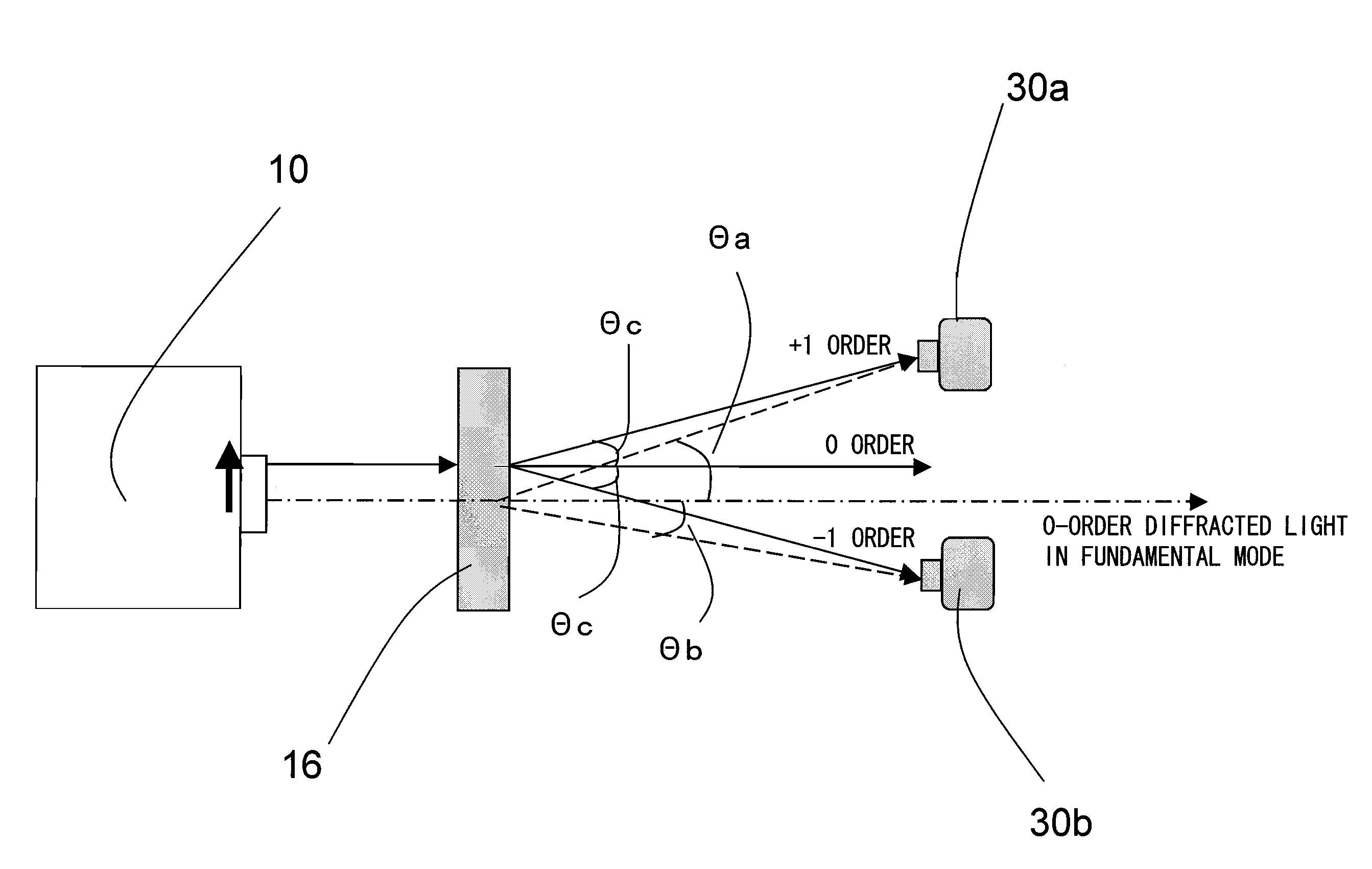
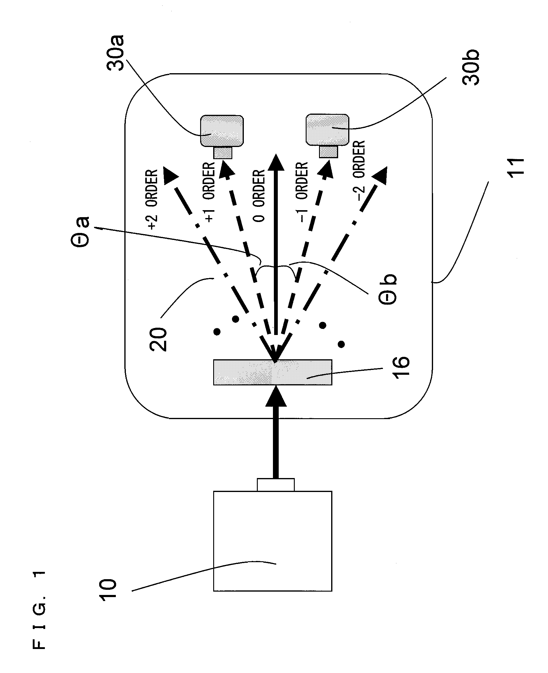
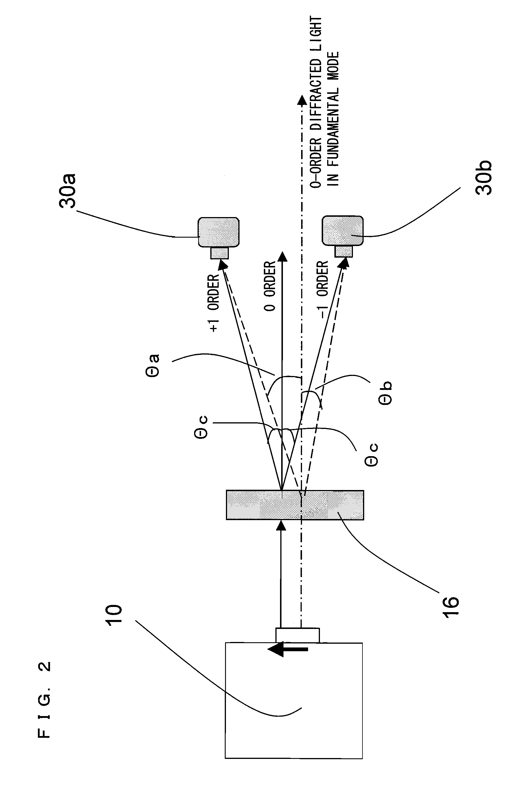
[0060]FIG. 1 is a schematic diagram showing an example structure of a wavelength detector 11 according to a first embodiment of the present invention. Referring to FIG. 1, the wavelength detector 11 includes a diffraction grating 16 for diffracting a laser light emerging from a laser light source 10, and also includes at least two photodetectors 30a and 30b which measure a +n-order diffracted light and a −n-order diffracted light, respectively (n is an integer equal to or greater than 1). The laser light emerging from the laser light source 10 is incident on the wavelength detector 11 provided in the light path of the laser light. In the wavelength detector 11, the laser light incident thereon is diffracted by the diffraction grating 16, and the diffracted laser lights interfere with one another and thus generate ±n-order diffracted lights 20. Light incidence surfaces of the photodetectors 30a and 30b which measure the diffracted lights 20 are each designed to be equal to or smaller...

second embodiment

[0068]FIG. 3 is a schematic diagram showing an example structure of a wavelength detector 12 according to a second embodiment of the present invention. Referring to FIG. 3, the wavelength detector 12 includes a diffraction grating 16 for diffracting a laser light emerging from a laser light source 10, and also includes at least two photodetectors 40a and 40b which measure a +n-order diffracted light and a −n-order diffracted light, respectively. The laser light emerging from the laser light source 10 is incident on the wavelength detector 12 provided in the light path of the laser light. In the wavelength detector 12, the laser light incident thereon is diffracted by the diffraction grating 16, and the diffracted laser lights interfere with one another and thus generate ±n-order diffracted lights 20. In this example, the photodetectors 40a and 40b measure a +1-order diffracted light and a −1-order diffracted light, respectively.

[0069]As shown in FIG. 3, on light incidence surfaces 4...

third embodiment

[0082]FIG. 7 is a schematic diagram showing an example structure of a wavelength detector 13 according to a third embodiment of the present invention. Referring to FIG. 7, the wavelength detector 13 includes a diffraction grating 16 for diffracting a laser light emerging from a laser light source 10, and also includes at least two photodetectors 50a and 50b which measure a +n-order diffracted light and a −n-order diffracted light, respectively. The laser light emerging from the laser light source 10 is incident on the wavelength detector 13 provided in the light path of the laser light. In the wavelength detector 13, the laser light incident thereon is diffracted by the diffraction grating 16, and the diffracted laser lights interfere with one another and thus generate ±n-order diffracted lights 20. In this example, the photodetectors 50a and 50b measure a +1-order diffracted light and a −1-order diffracted light, respectively.

[0083]Referring to FIG. 7, a beam spot 52a is the beam s...


PUM


Abstract

A wavelength detector detecting a change of a wavelength of a laser light with high accuracy, such that the wavelength detector includes a diffraction grating diffracting a laser light, photodetectors positioned symmetrically with respect to a 0-order diffracted light diffracted by the diffraction grating, and respective light incidence surfaces of the photodetectors that have a same shape and that are divided into a plurality of areas. The wavelength detector detects the change of the wavelength based on a value obtained by dividing a difference between (i) a sum of light intensities measured by all of the plurality of divided areas of a first photodetector and (ii) a sum of light intensities measured by all of the plurality of divided areas of a second photodetector, by a sum of light intensities measured by all of the plurality of divided areas of both photodetectors.

Description

BACKGROUND OF THE INVENTION[0001]1. Field of the Invention[0002]The present invention relates to a wavelength detector, a wavelength stabilization laser device, and an image display device, and particularly to a wavelength detector capable of distinguishing between the changes of a transverse mode and of a longitudinal mode of a laser light and thus detecting the change of the wavelength of the laser light, to a wavelength stabilization laser device using the wavelength detector, and to an image display device using the laser light generated by the wavelength stabilization laser device as a light source.[0003]2. Description of the Related Art[0004]In recent years, an image display device using laser light sources attracts attention. Since a laser light is a coherent light, the width (spectral width) of the wavelength of the laser light is extremely narrow. Since the wavelength determines a color, the laser light has excellent monochromaticity. The wavelengths of the laser light sour...

Claims


Application Information

Patent Timeline
IPC IPC(8): H01S3/08
CPCG01J1/04G01J1/0407G01J1/0437G01J1/4228G01J9/00G02F1/1336G01J1/0448H01S5/0687
Inventor NAKAYAMA, KENJIKADOWAKI, SHINICHI
Owner PANASONIC CORP
Why Eureka
Eureka Blog
Learn More