Scroll compressor

a compressor and compressor technology, applied in the direction of machines/engines, rotary/oscillating piston pump components, liquid fuel engines, etc., can solve the problems of increasing the size of the compressor, generating more vibration and noise, etc., and achieves a sufficient compression ratio and reduced compressor size

Active Publication Date: 2012-11-13
LG ELECTRONICS INC
View PDF20 Cites 15 Cited by
  • Summary
  • Abstract
  • Description
  • Claims
  • Application Information

AI Technical Summary

Benefits of technology

[0009]To overcome the drawbacks of the background art, a scroll compressor is provided that is capable of reducing an entire size of the compressor while ensuring a sufficient compression ratio. The orbiting scroll of the present invention is configured so that the orbiting wrap and the coupling portion for the rotation shaft are located at the same surface in the same plane. This arrangement allows the repulsive force of the refrigerant and the reaction force to be applied in the same plane so as to solve the inclination problem of the orbiting scroll of the background art.
[0024]In accordance with these aspects of the invention, the compression ratio of the first compression chamber can be increased as compared to a scroll compressor having a fixed wrap and an orbiting wrap having an involute shape. In addition, as a thickness of an inner end portion of the fixed wrap varies, wrap rigidity can be enhanced and leakage prevention capability can be improved.

Problems solved by technology

Hence, the number of turns of the wrap should increase to obtain a sufficient compression ratio, which may, however, cause the compressor to be increased in size corresponding to the increased number of turns of the wrap.
Because the boss is not in the same plane on the same surface as the orbiting wrap, the orbiting scroll is inclined during operation, thereby generating more vibration and noise.

Method used


Image

  • Scroll compressor
  • Scroll compressor
  • Scroll compressor

Examples


Embodiment Construction

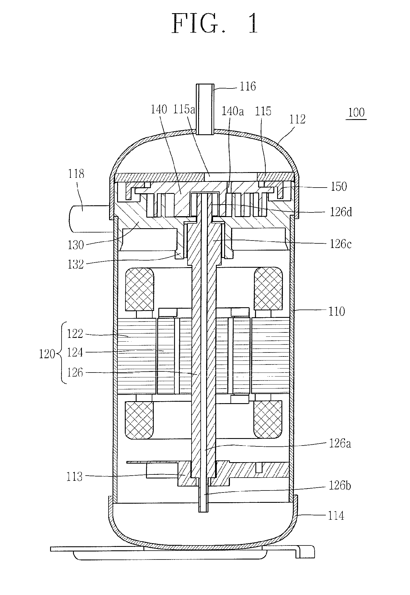
[0043]Hereinafter, description will be made in detail to the exemplary embodiments of a scroll compressor according to this invention with reference to the accompanying drawings.

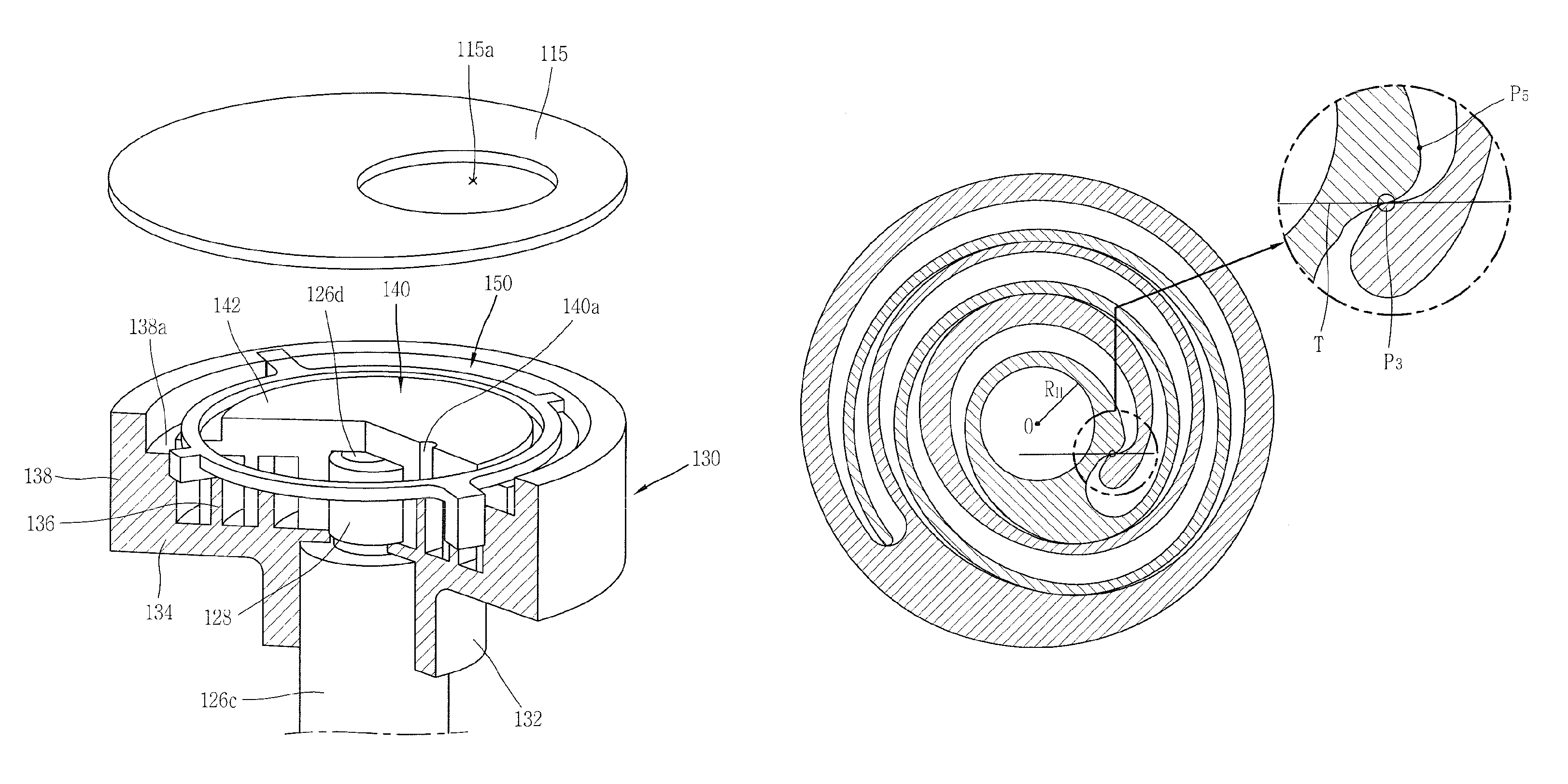
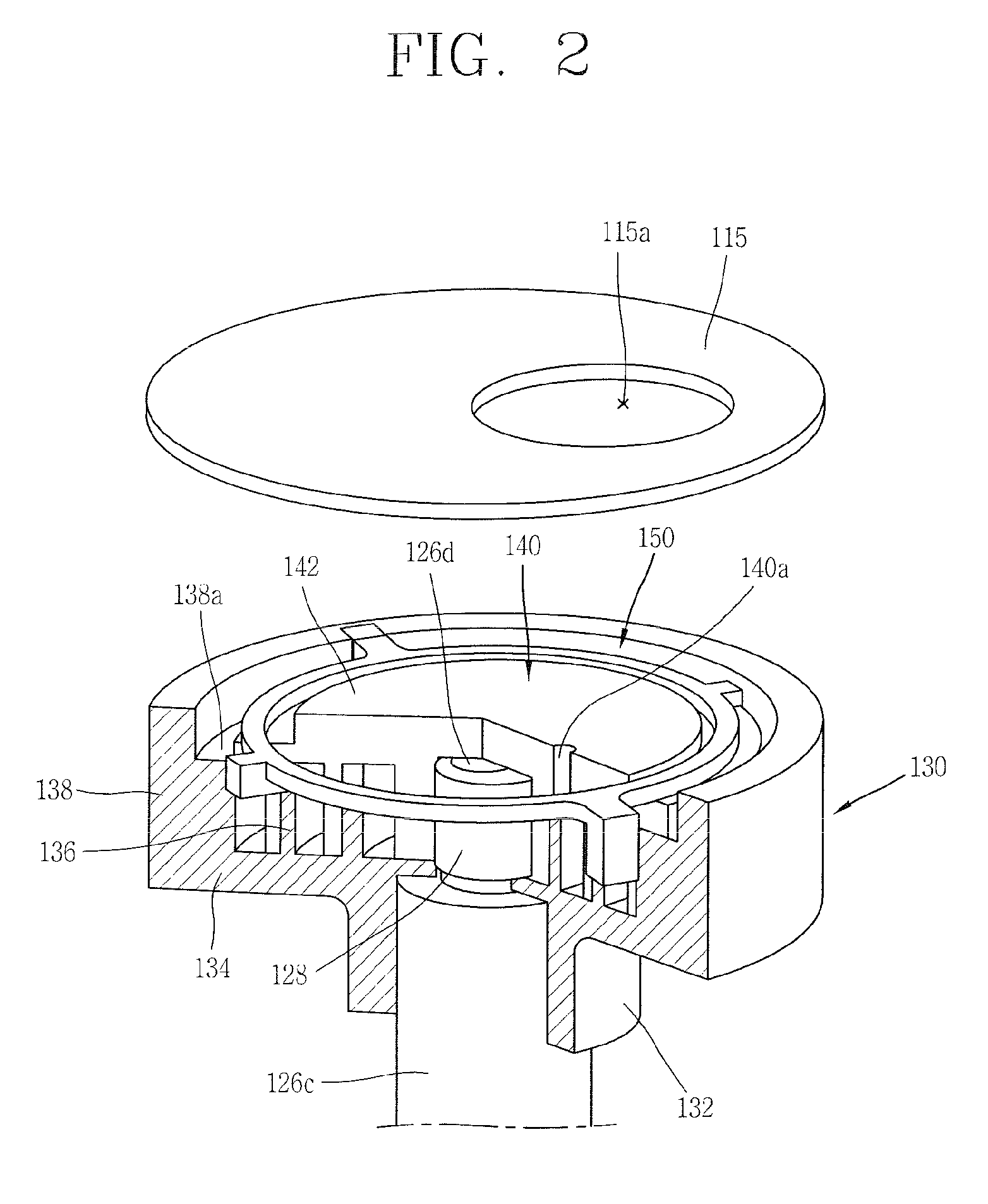
[0044]As shown in FIG. 1, the exemplary embodiment may include a hermetic compressor 100 having a cylindrical casing 110, and an upper shell 112 and a lower shell 114 for covering upper and lower portions of the casing 110. The upper and lower shells 112 and 114 may be welded to the casing 110 so as to define a single hermetic space together with the casing 110. A lower space of the hermetic compressor 100 may define a suction space, and an upper space thereof may define a discharging space. The lower and upper spaces may be divided based upon an upper frame 115 to be explained later.

[0045]A discharge pipe 116 may be connected to an upper side of the upper shell 112. The discharge pipe 116 may act as a path through which a compressed refrigerant is discharged to the outside. An oil separator (not shown) for ...


PUM


Abstract

A scroll compressor includes a fixed scroll having a fixed wrap, and an orbiting scroll having an orbiting wrap engaged with the fixed wrap to define a first compression chamber between an inner surface of the fixed wrap and an outer surface of the orbiting wrap, and to define a second compression chamber between an inner surface of the orbiting wrap and an outer surface of the fixed wrap. A rotation shaft is provided with an eccentric portion at one end thereof to drive the orbiting scroll. A protruding portion protrudes inwardly from an inner end of the fixed wrap, and contacts the orbiting wrap. A distance between a center of the eccentric portion and a tangent line at a contact point between the protruding portion and the orbiting wrap at an end of the first compression chamber is smaller than a radius of the eccentric portion.

Description

CROSS-REFERENCE TO RELATED APPLICATION[0001]Pursuant to 35 U.S.C. §119(a), this application claims the benefit of the earlier filing date and the right of priority to Korean Applications No. 10-2011-0021108, filed on Mar. 9, 2011, and 10-2011-0046492, filed on May 17, 2011 the contents of which is incorporated by reference herein in its entirety.BACKGROUND OF THE INVENTION[0002]1. Field of the Invention[0003]This invention relates to a scroll compressor, and more particularly, to a configuration of a fixed scroll and an orbiting scroll of the scroll compressor capable of obtaining a sufficient compression ratio.[0004]2. Background of the Invention[0005]A scroll compressor is a compressor which includes a fixed scroll having a fixed wrap and an orbiting scroll having an orbiting wrap engaged with the fixed wrap. In this configuration of the scroll compressor, as the orbiting scroll orbits on the fixed scroll, the volumes of compression chambers, which are formed between the fixed wra...

Claims


Application Information

Patent Timeline
Patent Type & Authority Patents(United States)
IPC IPC(8): F03C2/00F04C2/00F03C4/00
CPCF04C18/0215F04C18/0269F04C23/008F04C29/00F04C18/02F04C2/02
Inventor SEONG, SANGHUNKIM, CHEOLHWANLEE, BYEONGCHULHA, SAMCHUL
Owner LG ELECTRONICS INC
Why Eureka
Try Eureka