Apparatus for producing a three-dimensional object

a three-dimensional object and apparatus technology, applied in auxillary shaping apparatus, butter manufacturing, manufacturing material handling, etc., can solve the problems of uneven powder distribution, mechanically operated powder supply plate function tends to worsen, and mechanical functioning is deteriorated

Active Publication Date: 2012-11-13
ARCAM AB
View PDF36 Cites 129 Cited by
  • Summary
  • Abstract
  • Description
  • Claims
  • Application Information

AI Technical Summary

Benefits of technology

[0015]Due to this design, a part of the base surface, i.e. the resilient part, can be forced to be depressed in a controlled but simple way when the distribution member moves into the powder storage unit. This allows powder to be transferred below the distribution rake; the further the distribution member moves into the powder supply, the more powder will be transferred.
[0016]Compared to the device disclosed in WO 2006 / 121374, where powder is transferred above the distribution member, the inventive design provides for a better control of the size of the powder portion being transferred, in particular when using powder with poor flowability. One reason for this improved control is that the transfer of powder below the distribution member is to a higher extent forced, and thereby principally easier to control, than the transfer above the distribution member where the powder is allowed to flow more freely. Another reason is that the amount of powder being transferred in the inventive apparatus is less strongly dependent on the position of the distribution member. This means that the size of the powder portion transferred can be controlled in a more exact manner (because the amount transferred can be controlled by controlling the position of the distribution member, i.e. by controlling how far it moves into the powder supply, and because any variation in this position has a smaller effect on the amount of powder being transferred when forcing powder below the distribution member than when allowing powder to flow above).
[0020]Such a spring-suspended and / or bendable plate is suitable for being depressed / bent downwards when exposed to the force generated by the distribution member and for returning / bending back when not exposed to said force. The function of such resilient parts is very reliable compared to the mechanically operated, height-adjustable plate shown in JP 2003245981.
[0021]Preferably, a covering foil is arranged on top of the base surface. A purpose of such a foil is to prevent that powder particles find their way into any gap between the resilient part and the rest of the base surface. Another purpose is to form a softly curved, continuous surface free from sharp discontinuities when the resilient part is lowered below the level of the surrounding base surface.

Problems solved by technology

This causes problems in that shafts, hinges and other moveable parts, in particular of the feeding member, stop up resulting in a worsened mechanical functioning.
In addition to production interruptions this leads to problems in feeding a correct amount of powder to the distribution member, which in turn leads to an uneven powder distribution.
A drawback of such systems is that the function of the mechanically operated powder supply plate has a tendency to worsen in the rough environment, i.e. after some time of operation it will become difficult to accurately control the vertical movement of the plate.
Problems may arise with the device disclosed in WO 2006 / 121374 when using certain types of powder that do not flow very well.

Method used


Image

  • Apparatus for producing a three-dimensional object
  • Apparatus for producing a three-dimensional object
  • Apparatus for producing a three-dimensional object

Examples


Embodiment Construction

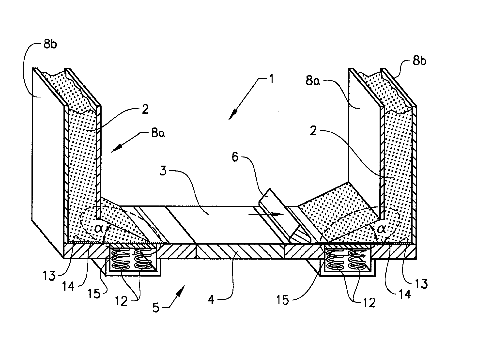
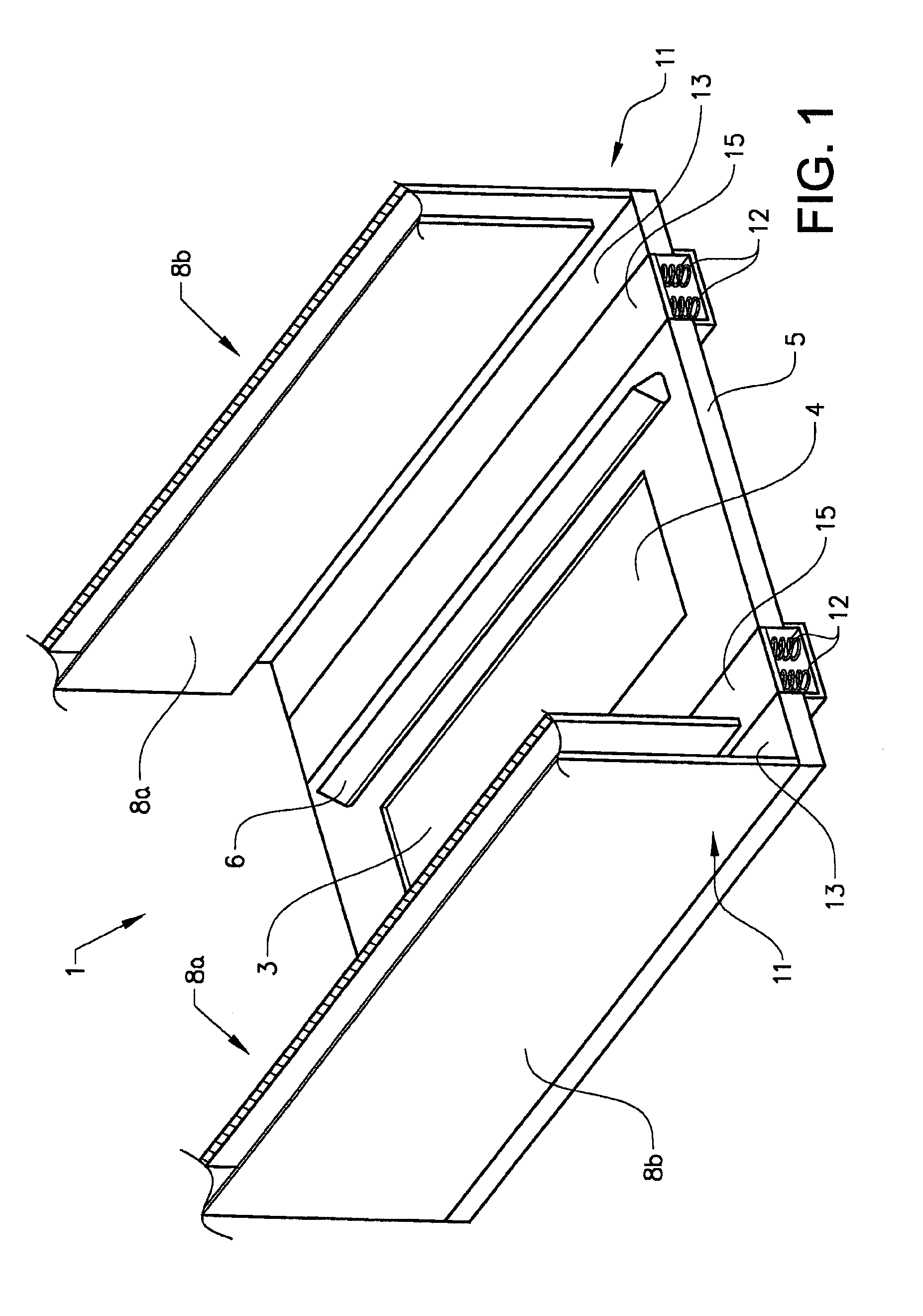
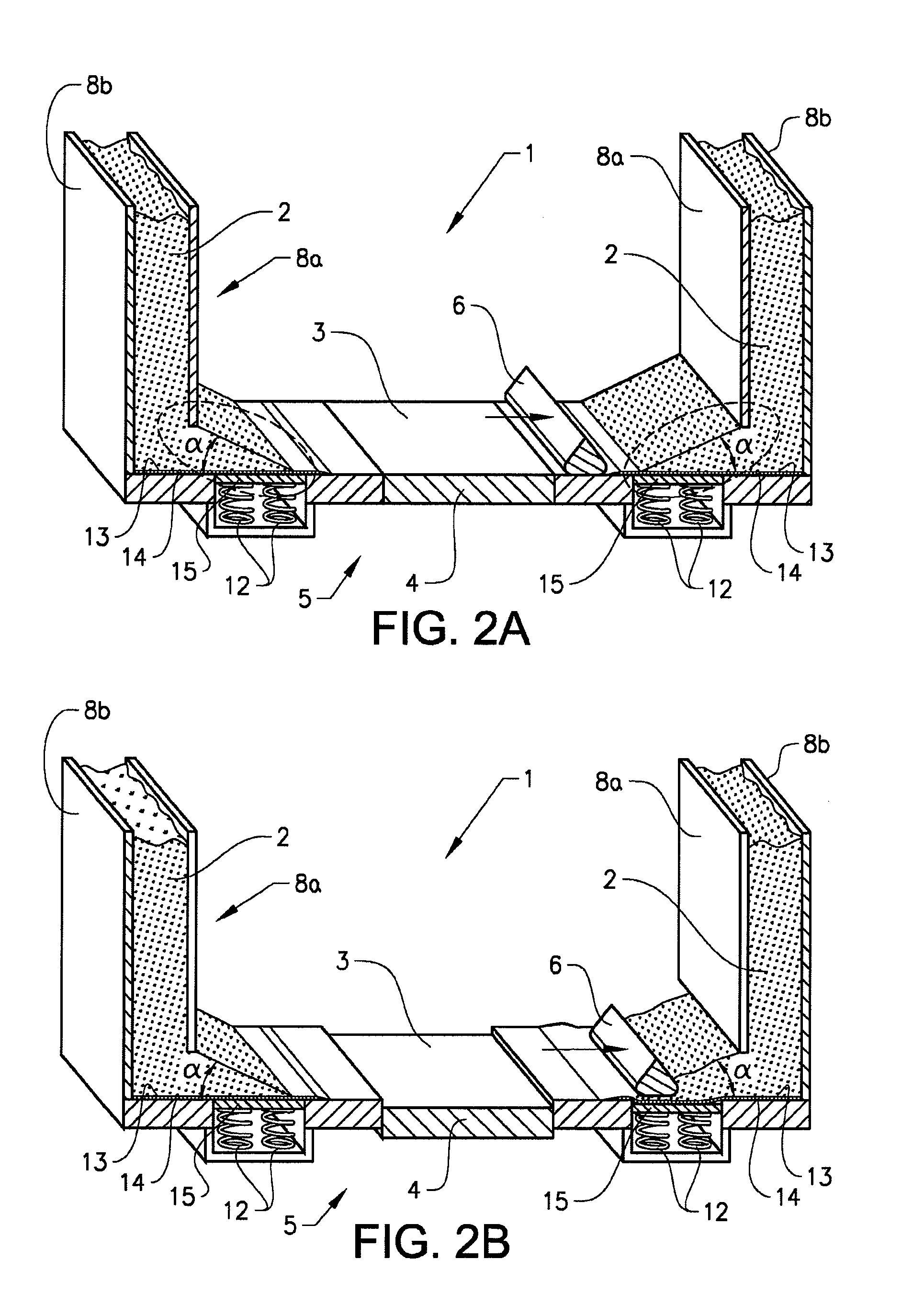
[0025]FIGS. 1 and 2 show the components and the function of a first advantageous embodiment of the invention. As shown in these figures the inventive apparatus 1 comprises a powder application system arranged on a substantially flat working table 5, which system comprises two powder storage units 11 symmetrically arranged on opposite sides of a working area 3 located on top of a vertically adjustable platform 4 that fits into a cut-out in the working table 5. Each powder storage unit 11 is adapted to contain a supply of powder 2 (see FIG. 2A). A distribution member 6 in the form of a rake with a triangular-like cross section extends along the working area 3 and is arranged by means of guides (not shown) to be moveable across the working area 3 in a direction perpendicular to its direction of extension and in a plane slightly above the working area 3.

[0026]A radiation source (not shown) is arranged in a conventional way at a distance above the working area 3, which working area 3 act...


PUM

PropertyMeasurementUnit
distanceaaaaaaaaaa
particle sizeaaaaaaaaaa
energyaaaaaaaaaa

Abstract

The invention concerns an apparatus (1) for producing a three-dimensional object layer by layer using a powdery material which can be solidified by irradiating it with an energy beam, such as electromagnetic radiation or an electron beam, said apparatus (1) comprising: a working area (3) onto which layers of powdery material are to be placed; a powder storage unit (11) comprising a base surface (13) for supporting a supply of powder (2); and a powder distribution member (6); wherein the base surface (13) extends along a side of the working area (3), wherein the distribution member (6) extends in a direction along the base surface (13) and said side of the working area (3) and is arranged to be moveable in a plane above, and substantially parallel to, the base surface (13) and the working area (3), and wherein the distribution member (6) is arranged to be moveable into a supply of powder (2) placed onto the base surface (13) such as to bring about a transfer of a portion of powder from a side of the distribution member (6) facing away from the working area (3) to an opposite side of the distribution member (6) facing the working area (3), said distribution member (6) further being arranged to be moveable towards and across the working area (3) so as to distribute the portion of powder onto the working area (3). The invention is characterized in that at least a part (15) of the base surface (13) is arranged to be resilient in a vertical direction.

Description

CROSS REFERENCE TO RELATED APPLICATIONS[0001]This application is a national stage application, filed under 35 U.S.C. §371, of International Application No. PCT / SE2009 / 050179, filed Feb. 18, 2009, which is hereby incorporated by reference in its entirety.BACKGROUND OF THE INVENTION[0002]1. Field of Invention[0003]This invention relates to an apparatus for producing a three-dimensional object layer by layer using a powdery material which can be solidified by irradiating it with an energy beam. In particular, the invention relates to the layerwize application of powder.[0004]2. Description of Related Art[0005]Equipment for producing a three-dimensional object layer by layer using a powdery material which can be solidified by irradiating it with electromagnetic radiation or an electron beam are known from e.g. U.S. Pat. Nos. 4,863,538, 5,647,931 and SE524467. Such equipment include for instance a supply of powder, means for applying a layer of powder on a working area, and means for dir...

Claims


Application Information

Patent Timeline
Patent Type & Authority Patents(United States)
IPC IPC(8): B28B1/16B29C35/08
CPCB29C67/0077B22F3/004B22F3/1055B22F2998/00B22F2003/1056B29C64/153B33Y30/00B29C64/343B29C64/205Y02P10/25B22F12/41B22F10/28
Inventor ACKELID, ULFWALLGREN, GORAN
Owner ARCAM AB
Why Eureka
Try Eureka