Millimetre-wave illumination source

a millimetre-wave illumination and millimeter-wave imaging technology, applied in the direction of individually energised antenna arrays, instruments, and reradiation, can solve the problems of difficult real-time interpretation of generated images, high energy consumption, and inability to provide recognisable images of passive non-metallic objects, so as to achieve careful control of aperture size and shape, the effect of less power

Inactive Publication Date: 2008-04-15
QINETIQ LTD
View PDF15 Cites 14 Cited by
  • Summary
  • Abstract
  • Description
  • Claims
  • Application Information

AI Technical Summary

Benefits of technology

[0028]Incoherence and non-directionality of the radiation from the apertures are two of the requirements noted above for good indoor illumination for passive millimeter-wave imaging and they can be achieved by the present invention while consuming much less power than is required in the heating or cooling of large areas of radar absorbent material.
[0029]It is also very desirable that the power of the millimeter-wave radiation emitted from each aperture in the container is similar so as to provide a uniformly radiating surface when viewed with a relatively low resolution (so as not to resolve individual apertures). This can be achieved in a variety of ways, such as by the careful arrangement of the pattern of the apertures formed in the container, by the use of at least one reflective baffle and/or at least one region of millimeter-wave absorbing material within the-container or by covering the apertu

Problems solved by technology

This does mean, however, that such imagers are not capable of providing recognisable images of passive non-metallic objects such as plastics, ceramics and explosives, which nowadays are often of more interest.
Passive millimeter-wave imaging can be accomplished indoors but the lack of sky illumination means that the m

Method used


Image

  • Millimetre-wave illumination source
  • Millimetre-wave illumination source
  • Millimetre-wave illumination source

Examples


Embodiment Construction

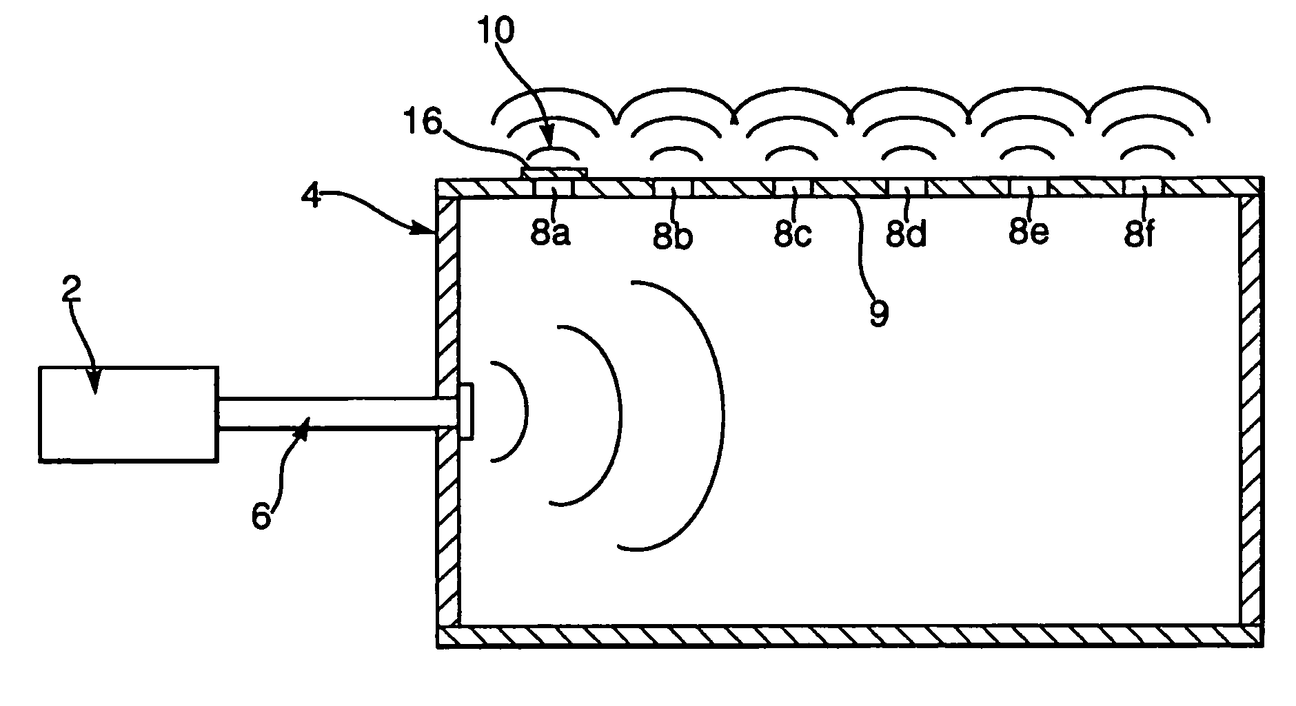
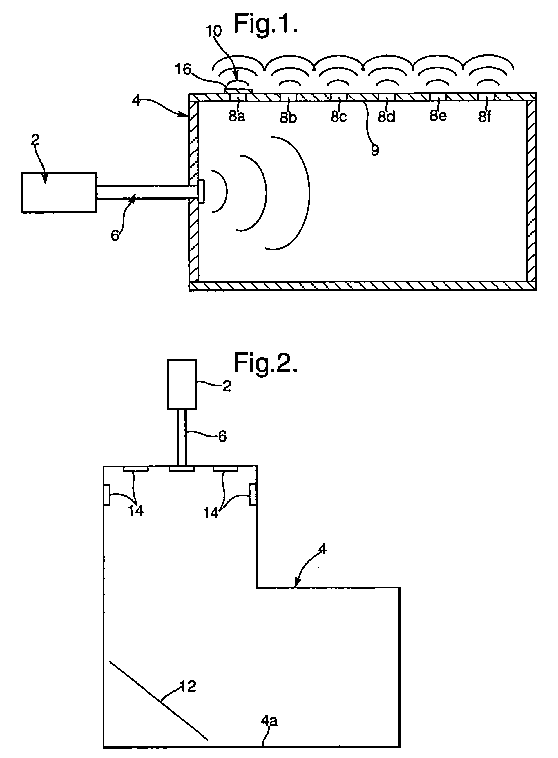
[0048]In the arrangement in FIG. 1 millimeter-wave electromagnetic radiation is generated in a millimeter-wave source 2, such as an amplified noise source and is coupled into a metal box 4 using waveguide 6. The source 2 will generate millimeter-wave radiation associated with a temperature which is either much higher or much lower than the ambient temperature of the objects in the area being imaged. In this way higher contrast can be introduced into the generated image. The metal box 4 has an internal reflective surface which may, for example, have a reflectivity of 0.5 or greater at the operating wavelength. At least one side of the box 9 is formed with an array of through holes or apertures 8, which may for example be circular, six of which (8a-8f) can be seen in FIG. 1. Normally the array will be two-dimensional, although the use of a one-dimensional or linear array also falls within the scope of the invention. The waveguide 6 has an aperture at its end remote from the source 2 h...


PUM


Abstract

An illumination source of predominantly non-directional and incoherent millimeter-wave radiation for illuminating an area for passive millimeter-wave imaging comprises a container with at least a partly reflective internal surface and a plurality of exit apertures and a primary source of millimeter-wave radiation for emitting millimeter-wave radiation into the container. The primary source and the container are arranged so that a proportion of the millimeter-wave radiation emitted by the source undergoes reflection within the container before being emitted through the apertures, such that the different paths lengths are at least equal to the coherence length of the radiation. This is facilitated if the bandwidth of the radiation is preferably at least 1 GHz. The container may be a box in which a waveguide is used to couple radiation from the primary source into the box. Alternatively, the container may be formed from a mesh and the plurality of holes is provided by the holes in the mesh.

Description

BACKGROUND OF THE INVENTION[0001]1. Field of the Invention[0002]The present invention relates to an illumination source for passive millimeter-wave imaging.[0003]2. Description of the Art[0004]Many available imagers for security applications can produce images which enable an operator to readily detect concealed weapons such as guns and knives, which are hidden for example within a person's clothing or baggage. Clothing and baggage materials are virtually transparent to at least some of these known imagers and this may be advantageous when metallic objects are solely of interest, since they will not be obscured by non-metallic material.[0005]This does mean, however, that such imagers are not capable of providing recognisable images of passive non-metallic objects such as plastics, ceramics and explosives, which nowadays are often of more interest.[0006]Millimeter-wave imaging addresses this problem. In outdoor passive millimeter-wave imaging high contrast is provided in the generate...

Claims


Application Information

Patent Timeline
IPC IPC(8): G01S13/88G01S13/89G01S7/35H01Q21/00G01S13/00G01V8/00H01Q21/06H01Q13/18G01S7/02G01S7/282
CPCG01S13/89G01V8/005H01Q13/18H01Q21/0012H01Q21/064G01S7/024G01S7/282G01S13/887
Inventor PRICE, SEANCOWARD, PETER RUSSELLSALMON, NEIL ANTHONY
Owner QINETIQ LTD
Why Eureka
Try Eureka