System and method for power conversion

a power conversion and system technology, applied in the direction of dynamo-electric converter control, dc-ac conversion without reversal, motor/generator/converter stopper, etc., can solve the problems of large low voltage cables used to transfer low voltage ac power to the ac/dc converter, waste of power resources,

Active Publication Date: 2012-11-13
GENERAL ELECTRIC CO
View PDF7 Cites 106 Cited by
  • Summary
  • Abstract
  • Description
  • Claims
  • Application Information

AI Technical Summary

Benefits of technology

[0007]In yet another embodiment, a method for power conversion is provided. The method includes splitting an input DC power into a plurality of portions of the input DC power. The method also includes converting each respective portion of the input DC power to a respective portion of converted AC power, wherein at least some of the portions of the input DC power are converted using a square waveform mode. The method further includes increasing the voltages of the respective portions of converted AC power. The method also includes combining the increased voltages in series to provide a combined AC power. The method further includes converting the combined AC power to provide output power for a power grid.

Problems solved by technology

Use of the inverters for pulse width modulation of the DC power in such embodiments may result in efficiency losses and further requires bulky and expensive filters to generate the sinusoidal AC power.
Furthermore, the low voltage cables that are used to transfer low voltage AC power to the AC / DC converters are large, heavy, and expensive.
In addition, the transformers are large and bulky.
Furthermore, in embodiments wherein an offshore AC / DC converter is installed to collect the AC power from various wind turbines and convert the AC power to DC power suitable for long distance transmissions, extra costs are incurred.

Method used


Image

  • System and method for power conversion
  • System and method for power conversion
  • System and method for power conversion

Examples


Embodiment Construction

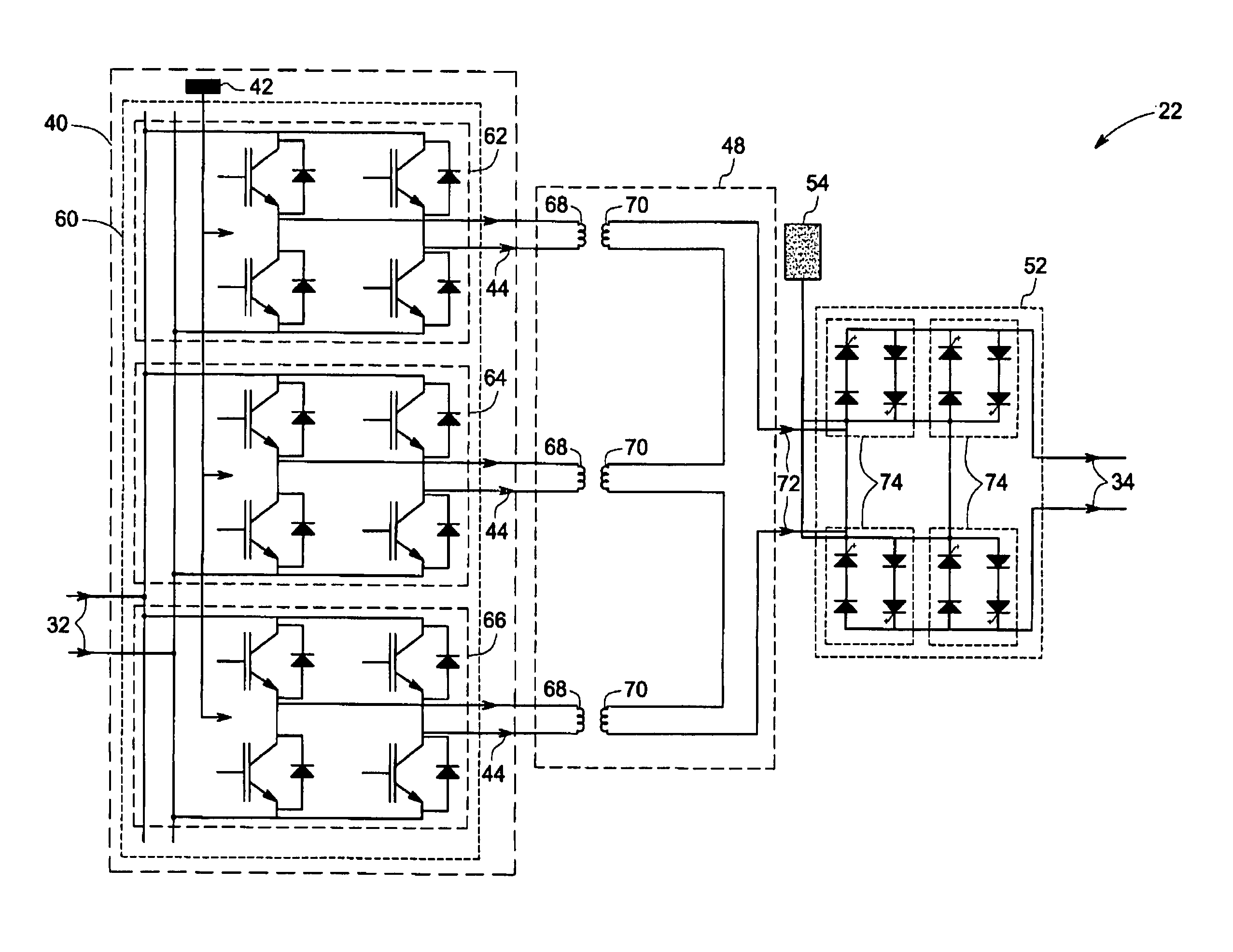
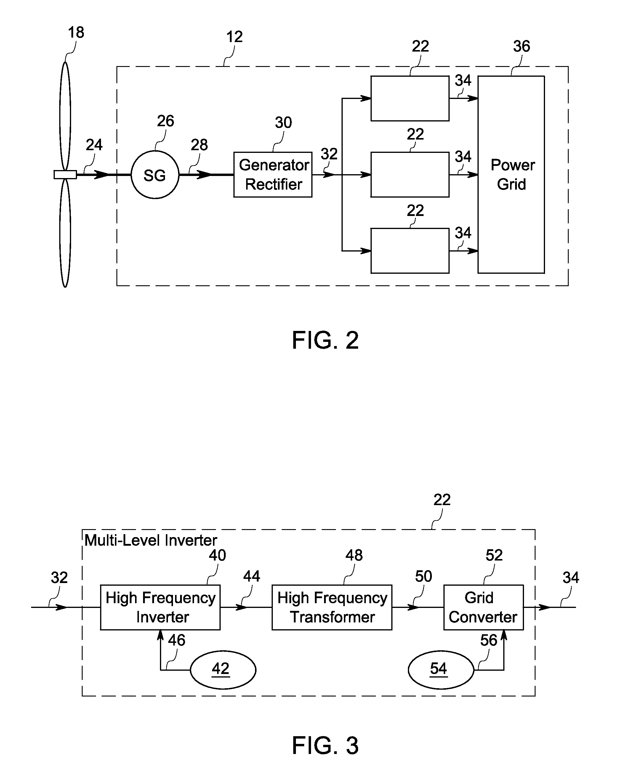
[0017]Embodiments of the present invention include a multilevel inverter. The multilevel inverter includes a plurality of bridges wherein each bridge receives a respective portion of an input DC power and converts the respective portion to a respective converted AC power. The multilevel inverter also includes at least one bridge controller that controls the operation of at least one of the plurality of bridges in a square waveform mode. The multilevel inverter further includes a plurality of transformers wherein each of the plurality of transformers includes a primary winding that is electrically coupled to a respective bridge. The primary winding is paired with a secondary winding that is electrically coupled in series with the other secondary windings. The primary winding receives the respective portion of the converted AC power and transfers the same to the secondary winding resulting in an increase in a voltage level of the respective portion of the converted AC power. The respe...


PUM


Abstract

A multilevel inverter is provided. The multilevel inverter includes a plurality of bridges, each bridge configured to receive a respective portion of an input DC power and convert the respective portion to a respective converted AC power. The multilevel inverter also includes at least one bridge controller for operating at least one of the plurality of bridges in a square waveform mode. The multilevel inverter further includes a plurality of transformers, each transformer coupled to a respective bridge and configured to increase a voltage level of the respective portion of converted AC power. The plurality of transformers further includes secondary windings coupled in series with the other secondary windings to combine the respective increased voltage level portions of the converted AC power. The multilevel inverter also includes a grid converter configured to provide output power for a power grid.

Description

BACKGROUND[0001]Embodiments of the present invention relate generally to a system for generating high voltage power in a fluid turbine.[0002]Fluid turbines, such as wind turbines and marine hydrokinetic devices, generate electricity from kinetic energy of fluids such as wind and water that is transmitted to power grids for distribution. For example, a wind turbine typically includes a rotor component that converts the kinetic energy of the wind to mechanical energy and a synchronous generator that converts the mechanical energy to an alternating current (AC) power with varying frequency and a low voltage. The AC power generated by the synchronous generator is adjusted through a power conversion system before being transmitted to one ore more power grids for further distribution.[0003]In one conventional power conversion system, the low voltage and varying frequency AC power is fed to an AC to DC converter disposed within the tower of the wind turbine via a low voltage cable. In a no...

Claims


Application Information

Patent Timeline
Patent Type & Authority Patents(United States)
IPC IPC(8): H02J1/00H02J3/00
CPCH02M7/49H02J3/386Y02E10/763H02J2300/28H02J3/381Y02E10/76
Inventor RAJU, RAVISEKHAR NADIMPALLI
Owner GENERAL ELECTRIC CO
Why Eureka
Try Eureka