Cold plate and refrigeration system

a technology of cold plate and refrigeration system, which is applied in the direction of lighting and heating apparatus, semiconductor/solid-state device details, and domestic cooling apparatus, etc., can solve the problems of more than 55% of damage, increase in power dissipation of electronic components, and performance problems caused by high temperature and power dissipation, etc., to improve the heat dissipation quality of the same

Active Publication Date: 2012-11-20
IND TECH RES INST
View PDF5 Cites 3 Cited by
  • Summary
  • Abstract
  • Description
  • Claims
  • Application Information

AI Technical Summary

Benefits of technology

[0004]In view of the aforesaid description, the present invention relates to a cold plate and a refrigeration system using the same, capable of preventing moisture in surrounding to condense directly on the cold plate so as to improve the heat dissipation quality of the same.
[0008]Accordingly, in the cold plate and the refrigeration system using the same, the design for enabling the temperature of the coolant flowing in the first fluid space to be higher than its dew point temperature is for preventing moisture in surrounding air from condensing. Moreover, by the pressure dropping of the expansion unit, the temperature of the coolant flowing through the expansion unit and then into the second fluid space is dropped to lower the dew point temperature for greatly improving the heat dissipation effect.
[0009]In addition, the double-pipe design adopted in the present invention, i.e. the disposition of the second pipe inside the first pipe, is used for enabling the coolant whose temperature is lower than the dew point temperature to flow in the second pipe while allowing those whose temperature is higher than the dew point temperature to flow in the first pipe that is outside the second pipe so that both pipes can be prevented from condensation.

Problems solved by technology

However, the ever increasing high-speed operation frequency and the reduction of circuit line width will cause the power dissipation of electronic components to increase.
Notably, in those electronic components that are damaged during operation, there are more than 55% of such damage are caused by overheating.
In addition, except for the IC chips, the same performance problem caused by high temperature and power dissipation can also been find in other devices, such as light emitting diode (LED), solar cell module, etc.
Both systems can only dissipate heat from a heat source and thus cause the temperature of the same to cool down to nearly it's ambient room temperature so that both systems may not have good heat dissipation efficiency especially for those high performance, high operation temperature electronic components.
However, such refrigeration system is disadvantageous in that: it can cause moisture in the surrounding air of the electronic component to condense thereon and thus cause instability or even malfunction to the electric circuits in the electronic component, which is true especially for those cold plates that are disposed in direct contact with electronic components for heat dissipation.
Since there can be many water drops being condensed on the surface of such clod plate that are more than likely to flow on the electronic component relating to the clod plate, such as IC chip or circuit board, circuit instability or malfunction in those IC chips or circuit board can be caused inevitably.
Consequently, the application of such refrigeration system in electronic component is restricted.

Method used


Image

  • Cold plate and refrigeration system
  • Cold plate and refrigeration system
  • Cold plate and refrigeration system

Examples


Embodiment Construction

[0015]For your esteemed members of reviewing committee to further understand and recognize the fulfilled functions and structural characteristics of the invention, several exemplary embodiments cooperating with detailed description are presented as the follows.

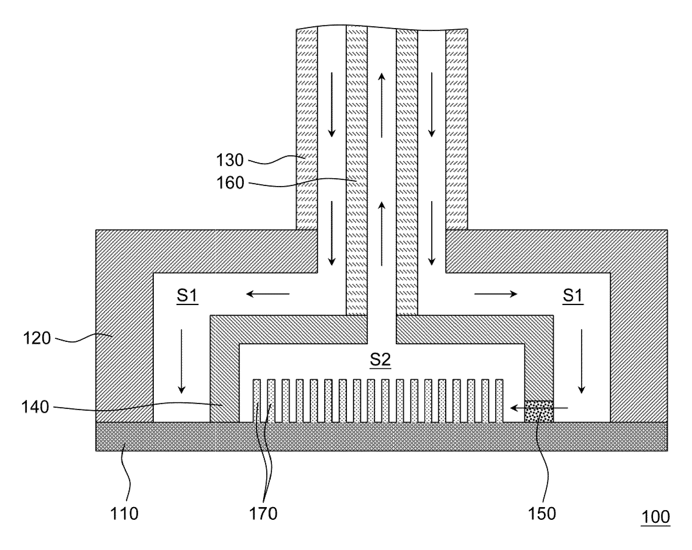
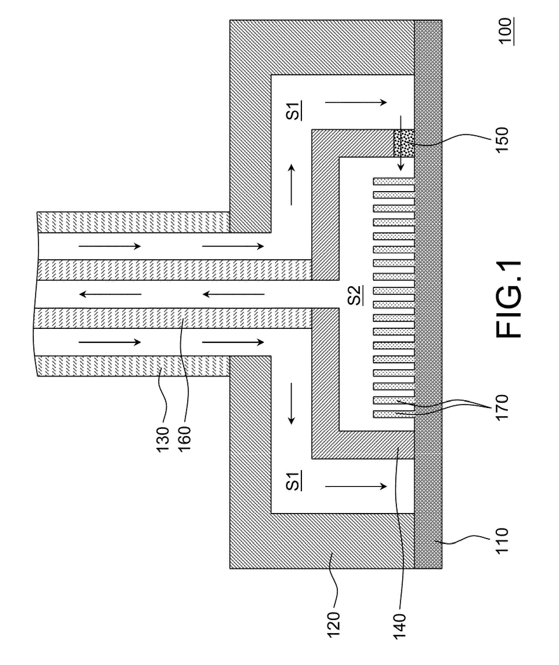
[0016]Please refer to FIG. 1, which is a sectional view of a cold plate according to an embodiment of the invention. In FIG. 1, the cold plate 100 includes a cold wall 110, a first cavity 120, a first pipe 130, a second cavity 140, an expansion unit 150 and a second pipe 160. It is noted that the cold plate 100 adopts a double-cavity, double-pipe design and it uses the expansion unit 150 as a medium for pressure dropping a coolant flowing in the cold plate 100 and thus enabling the temperature of the coolant to change in different spaces in the cold plate 100. Moreover, the coolant is flowing in directions indicated by the arrows in FIG. 1.

[0017]Basically, the first cavity 120 is arranged covering on the cold wall 110 for form...


PUM


Abstract

A cold plate including a cold wall, a first cavity, a first pipe, a second cavity, an expansion unit and a second pipe is provided. The first cavity covers on the cold wall to form a first fluid space, and the first pipe is connected with the first cavity. The second cavity is disposed inside the first cavity and covers on the cold wall to form a second fluid space. The expansion unit is disposed between the second cavity and the cold wall to interconnect the first fluid space and the second fluid space. The second pipe is disposed inside the first pipe and connected with the second cavity. Besides, a refrigeration system including the cold plate mentioned above is also provided.

Description

FIELD OF THE INVENTION[0001]The present invention relates to a refrigeration system and its cold plate, and more particularly, to a refrigeration system and its cold plate with anti-condensation ability.BACKGROUND OF THE INVENTION[0002]With rapid advance of packaging technology and manufacturing process in integrated circuit (IC) industry, the IC packaging density and the operation speed of an electronic component are increasing rapidly therewith. However, the ever increasing high-speed operation frequency and the reduction of circuit line width will cause the power dissipation of electronic components to increase. Notably, in those electronic components that are damaged during operation, there are more than 55% of such damage are caused by overheating. Moreover, as indicated in many researches, the operation efficiency of a chip can be increased by 1% to 3% whenever its temperature is reduced by 10° C. which may lead to an conclusion that the life expectancy as well as the operatio...

Claims


Application Information

Patent Timeline
Patent Type & Authority Patents(United States)
IPC IPC(8): F25D11/00
CPCF28F3/12H01L23/427F28D2021/0029F28D2021/0071H01L2924/0002H01L2924/00
Inventor YANG, KAI-SHINGWANG, CHI-CHUANLIN, SHIH-JIEWU, YU-LIEH
Owner IND TECH RES INST
Why Eureka
Try Eureka