Method for the production of a rotationally symmetrical part, and part produced according to said method

a rotational symmetry and hollow part technology, applied in the direction of screw threads, mechanical instruments, other domestic objects, etc., can solve the problems of high production cost of transmission shafts, inability to produce bores or through bores or hollow parts, and high weight, so as to reduce weight, save materials for parts and production costs, and maintain strength

Inactive Publication Date: 2012-11-20
GESENKSCHMIEDE SCHNEIDER GMBH
View PDF32 Cites 2 Cited by
  • Summary
  • Abstract
  • Description
  • Claims
  • Application Information

AI Technical Summary

Benefits of technology

[0008]In view of the foregoing, the present invention seeks to provide a method for the production of a rotationally symmetrical hollow metal part for the easier production of light parts of solid material of high strength.
[0016]By the introduction of the mandrel into the weakened internal zone in which, because of oscillating rolling at an elevated temperature (in case of steel in the range between 900 and 1150° C.), the crystal lattice of the forgeable metal materials is weakened, the through-hole boring can be reached whereby a comparatively thick-walled rotationally symmetrical hollow part, like a hollow shaft, can be produced with a high level of precision. This weakening of the core zone of the bar during the transversally spline-rolling or its oscillating rolling effect is also known as the Mannesmann effect. Because of the high level of external pressure on the bar during the transversally spline-rolling process, the peripheral (mantle) layer of the bar-shaped material is hardened, whereby the parting of the walls is facilitated. By the insertion of the mandrel a high level of workpiece precision is achieved because the material is still formed by the external forming tools, while the hardening produced by the hot-rolling process produces shafts with corresponding strength. A typical number of rotations of the starting material up to the finished tube amounts to approximately 5-10 for chrome steel—by these rotations, the mandrels produce a bore-hole of sufficient depth or a through bore-hole wherein the continuation of the advancement of the mandrels is very advantageous for the production of bore-holes.
[0017]It is advantageous that the mandrels can be inserted with a relatively low pressure into the bar-shaped material; whereby a straight bore-hole is achieved with a relatively reduced effort.
[0021]As a consequence, the method is easy to be executed for a high numbers of parts, whereby the applied forming process produces an essentially net-shaped end shape and the so produced parts in general do not have to be reworked, so that Important savings of materials for the part and production costs are obtainable.
[0022]The hollow shaft reduces the weight as compared to the traditional shafts of solid material, and at the same time, their strength is maintained. By the insertion of the mandrels, the material in the core zone is displaced to the peripheral zone, so that a high level of precision is achieved because the material is pressed against external forming tools.
[0023]It is advantageous that two mandrels are inserted along the ends of the bar-shaped solid material. In this way, the travel of a mandrel is shortened and a higher cycle time is obtained. In this way, the mandrels are inserted without having direct contact one with the other. In the further run, one mandrel is driven back and the other mandrel is inserted onwards over an overlapping zone.

Problems solved by technology

By the use of solid material, a high weight is obtained, which is undesirable especially in the application of these kinds of shafts in the automotive industry.
Transmission shafts are also costly when produced by round kneading machines from hollow shafts and then welded or the shafts are mechanically machined (deep-hole drilled).
The axially arranged mandrels provide only supporting devices and optionally as processing devices for the end sectors or the bar—the production of a bore-hole or a through bore-hole or of a hollow part is not possible.
Also costly temperature guidance is necessary for the execution of this process.

Method used


Image

  • Method for the production of a rotationally symmetrical part, and part produced according to said method
  • Method for the production of a rotationally symmetrical part, and part produced according to said method
  • Method for the production of a rotationally symmetrical part, and part produced according to said method

Examples


Embodiment Construction

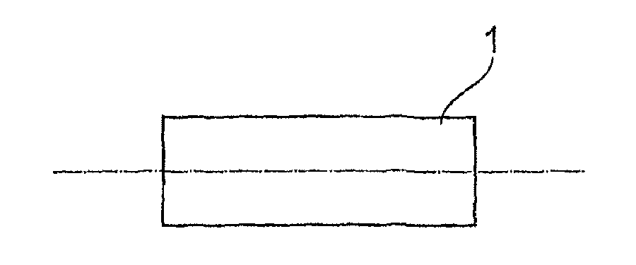
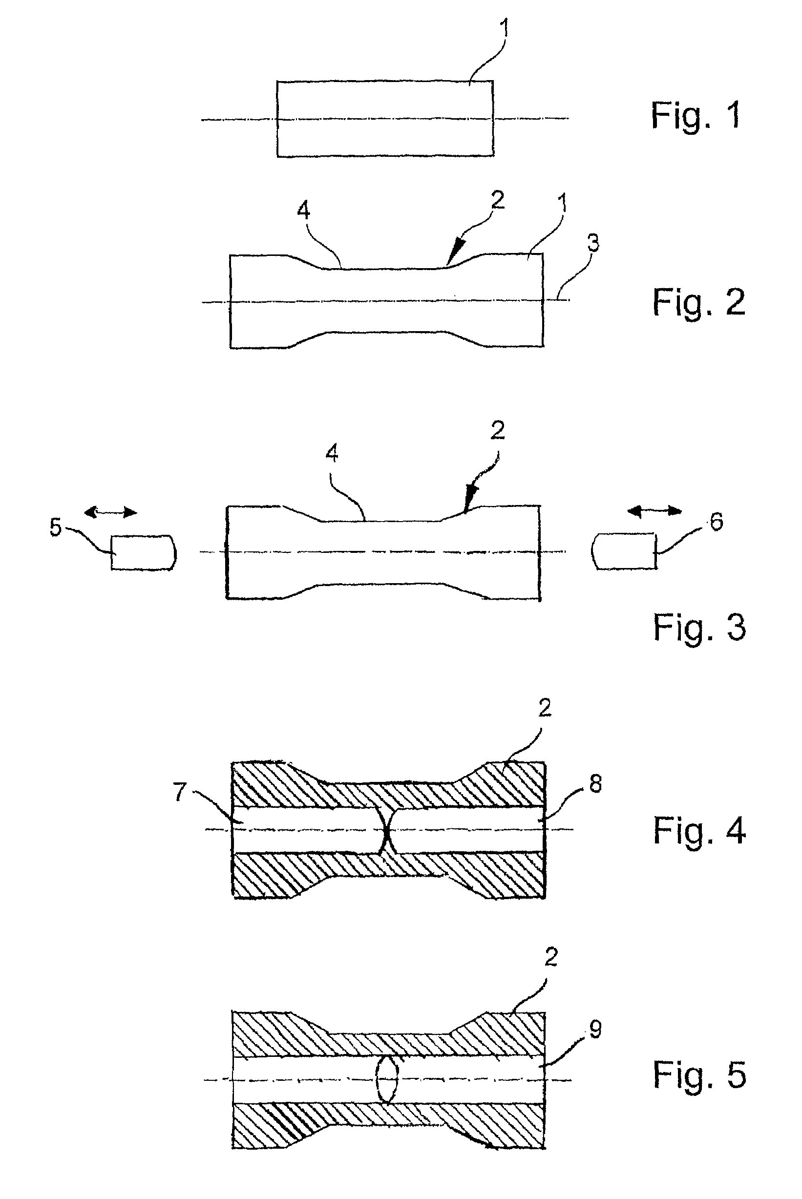
[0035]In FIG. 1, a bar 1 of solid material is shown, which is heated to the forging temperature. In FIG. 2, it is schematically shown how the material is formed into a transversally spline-rolled shaft of different diameters. During the rolling process, the bar 1 is moved with high forces over the tools 12, 14 so that the material is hardened in the peripheral zone 4 and the core 3 becomes brittle because of the oszillating movement and is torn open. The tools 12, 14 form the peripheral part of the shaft 2 similar to its end shape. In this way collars, thinnings, etc. can be formed. A typical wall thickness of such a shaft amounts to 5-10 mm.

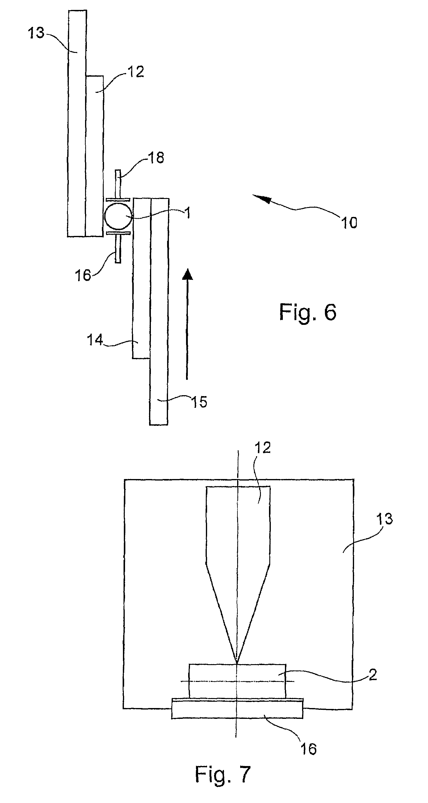
[0036]FIG. 3 shows how, from the two axial end surfaces of the shaft 2, two rotatable, moveable mandrels 5, 6 are forcibly introduced in an axial direction into the shaft 2 along the center axis 3 weakened by the Mannesmann effect. The mandrels 5, 6 continue advancing to a point before they contact. In this way, the shaft material is pressed mor...


PUM

PropertyMeasurementUnit
diameteraaaaaaaaaa
diameteraaaaaaaaaa
diameteraaaaaaaaaa

Abstract

A method for producing a rotationally symmetrical hollow metal part, particularly a shaft. According to the method, bar-shaped ductile solid material is provided, the solid material is heated from about 300° C. below the forging temperature to the forging temperature, the solid material is transversally spline-rolled until weakenings are created in the core zone (3) of the solid material and the sold material is torn open. Two mandrels (5,6) are forcibly introduced into the center of the bar-shaped solid material during the rolling process, and then one mandrel is retracted while the other mandrel continues advancing so as to produce a tubular part. A transversally spline-rolled rotationally symmetrical hollow part, especially a shaft, which is produced according to noted method can be embodied as a transmission shaft, camshaft, drive shaft, output shaft, starter shaft, hollow shaft, or can be a preform for molded parts and the like.

Description

BACKGROUND OF THE INVENTION[0001]1. Field of Invention[0002]The invention relates to a method for producing a rotationally symmetrical hollow part, particularly a shaft or a transversally spline-rolled rotationally symmetrical hollow part.[0003]2. Description of Related Art[0004]The production of rotationally symmetrical hollow parts from solid material which can also serve, for example, as a preform for further forming, like stepped shafts, especially of a transmission shaft by transversal spline-rolling is increasingly executed. It is executed on plane jaw or round jaw machines. These transversally spline-rolled shafts are hardened by a rolling process performed on its periphery. By the use of solid material, a high weight is obtained, which is undesirable especially in the application of these kinds of shafts in the automotive industry. Transmission shafts are also costly when produced by round kneading machines from hollow shafts and then welded or the shafts are mechanically ma...

Claims


Application Information

Patent Timeline
Patent Type & Authority Patents(United States)
IPC IPC(8): B21D17/04
CPCB21H1/18
Inventor KOERNER, THOMASSCHMITZ, ERNST-PETERKOLBE, PETER
Owner GESENKSCHMIEDE SCHNEIDER GMBH
Why Eureka
Try Eureka