
Debris filter

a filter and debris technology, applied in the field of nuclear reactor cores, can solve the problems of fuel bundle failure, debris accumulation, complex assembly, etc., and achieve the effects of improving the filtering effectiveness, improving the manufacturability and assembly of debris, and improving the filtering

Active Publication Date: 2012-11-27
GLOBAL NUCLEAR FUEL -- AMERICAS
View PDF35 Cites 16 Cited by
  • Summary
  • Abstract
  • Description
  • Claims
  • Application Information

AI Technical Summary

Benefits of technology

[0005]The various embodiments of the present invention provide a debris filter for filtering coolant entering the core of a nuclear reactor. The inventors hereof have designed a debris filter that provides, in various embodiments, for improved effectiveness in filtering debris, while simultaneously improving its manufacturability and assembly. Additionally, in some embodiments of the invention, the debris filter improves filtering effectiveness without substantially increasing the pressure drop and / or decreasing the pressure drop of the fluid flow in the lower tie plate assembly to enable flexibility in the overall fine-tuning of the bundle thermal hydraulic design.

Problems solved by technology

Over time, debris accumulates in the reactor and can result in fuel bundle failures in the field by debris fretting through the fuel rod cladding.
The coolant moderator circulation system in a nuclear reactor is closed and debris accumulates over time with increasing age and use of the reactor.
While certain advantages accrue to this type of debris catcher, the various parts are difficult to manufacture and require complex assembly.
While this is effective in filtering out debris, the wires of the debris filter themselves have been known to generate debris, resulting in fuel bundle failures.
The hole size and small ligament web between the holes, however, are very near the investment casting manufacturability limits and oftentimes require hand rework to produce the filter.
While this design is simple and robust and does not add additional piece parts to the lower tie plate, any reduction in size of the debris filtering holes would render the lower tie plate very difficult to cast.

Method used


Image

  • Debris filter
  • Debris filter
  • Debris filter

Examples


Embodiment Construction

[0021]The following description is merely exemplary in nature and is in not intended to limit the invention, its applications, or uses.

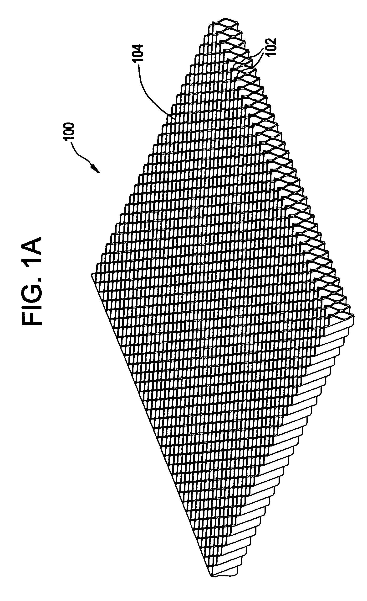
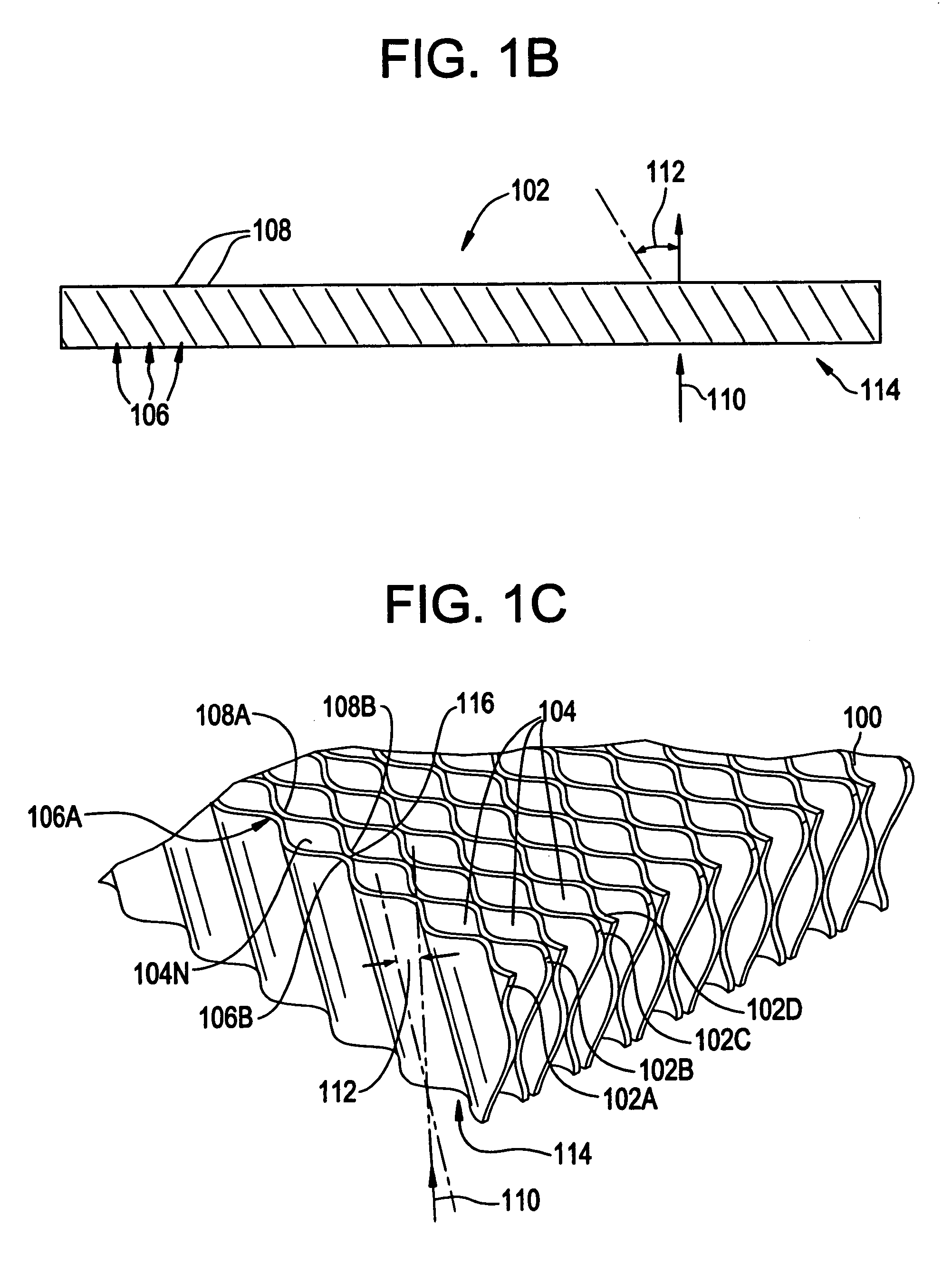
[0022]In some embodiments of the invention, a debris filter for reactor coolant includes a plurality of adjacent plates defining a plurality of channels therebetween, each of said channels being at an angle to a flow path of the coolant into the filter. One such exemplary embodiment is illustrated in FIGS. 1A, 2B, and 1C.

[0023]Referring to FIG. 1A, a filter 100 includes a plurality of plates 102 defining a plurality of flow channels 104 therebetween. In this illustrated embodiment, the filter 100 is rectangular in shape; however, the filter 100 can be formed in any shape or size adaptable for use within a nuclear reactor. A single plate 102 of the filter 100 is shown in FIG. 1B. Each plate 102 has a plurality of alternating peaks 106 and valleys 108 spaced at a predetermined spacing from one another. The peaks 106 and valleys 108 are configured such ...


PUM


Abstract

A debris filter for reactor coolant includes a plurality of adjacent plates defining a plurality of channels therebetween, each of said channels being at an angle to the flow path of the coolant into the filter.

Description

FIELD OF THE INVENTION[0001]The present invention relates to a nuclear reactor core and more specifically relates to a debris filter for coolant entering the core of a nuclear reactor.DESCRIPTION OF RELATED ART[0002]In a nuclear reactor, a liquid coolant or moderator flows into the reactor core from the bottom and exits the core as a water / steam mixture from the top. The core includes a plurality of fuel bundles arranged in vertical side-by-side relation, each containing a plurality of fuel rods. The fuel bundles are each supported between an upper tie plate and a lower tie plate. The lower tie plate typically includes an upper grid, a lower inlet nozzle and a transition region between the inlet nozzle and the grid whereby coolant water entering the inlet nozzle flows through the transition region and through the grid generally upwardly and about the individual fuel rods of the fuel bundle supported by the lower tie plate.[0003]Over time, debris accumulates in the reactor and can re...

Claims


Application Information

Patent Timeline
Patent Type & Authority Patents(United States)
IPC IPC(8): B01D46/10B01D29/07G21C19/04
CPCG21C3/3206G21Y2002/201Y02E30/40G21Y2002/304G21Y2004/30G21Y2002/302Y02E30/30
Inventor ELKINS, ROBERT BRUCELONGREN, RICHARD CARL
Owner GLOBAL NUCLEAR FUEL -- AMERICAS
Learn More