Composite structures with ordered three-dimensional (3D) continuous interpenetrating phases

Active Publication Date: 2012-11-27
HRL LAB
View PDF54 Cites 73 Cited by
  • Summary
  • Abstract
  • Description
  • Claims
  • Application Information

AI Technical Summary

Benefits of technology

[0019]In one embodiment, the ceramic material is formed by: forming a green body by filling the open volume of the three-dimensional order

Problems solved by technology

However, the above discussed composite structures do not provide for a composite structure with two interpenetrating phase

Method used


Image

  • Composite structures with ordered three-dimensional (3D) continuous interpenetrating phases
  • Composite structures with ordered three-dimensional (3D) continuous interpenetrating phases
  • Composite structures with ordered three-dimensional (3D) continuous interpenetrating phases

Examples


Embodiment Construction

[0036]In the following detailed description, only certain exemplary embodiments of the present invention are shown and described, by way of illustration. As those skilled in the art would recognize, the described exemplary embodiments may be modified in various ways, all without departing from the spirit or scope of the present invention. Accordingly, the drawings and description are to be regarded as illustrative in nature, and not restrictive.

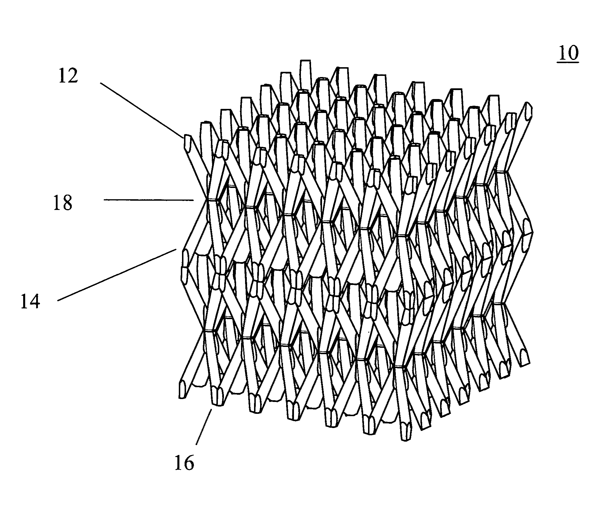
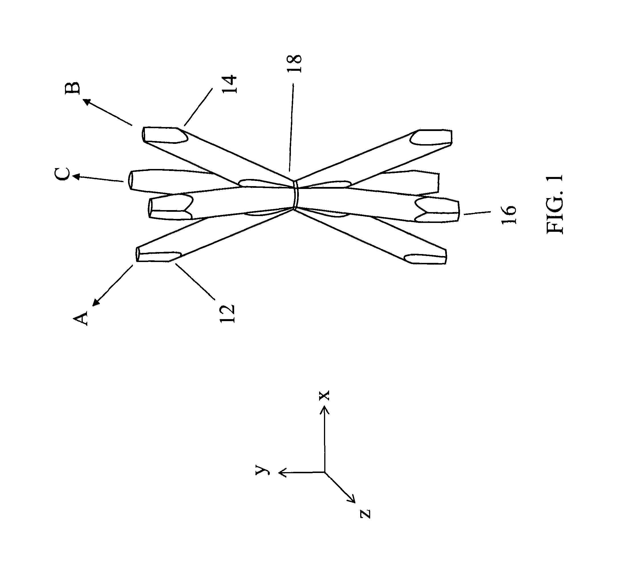
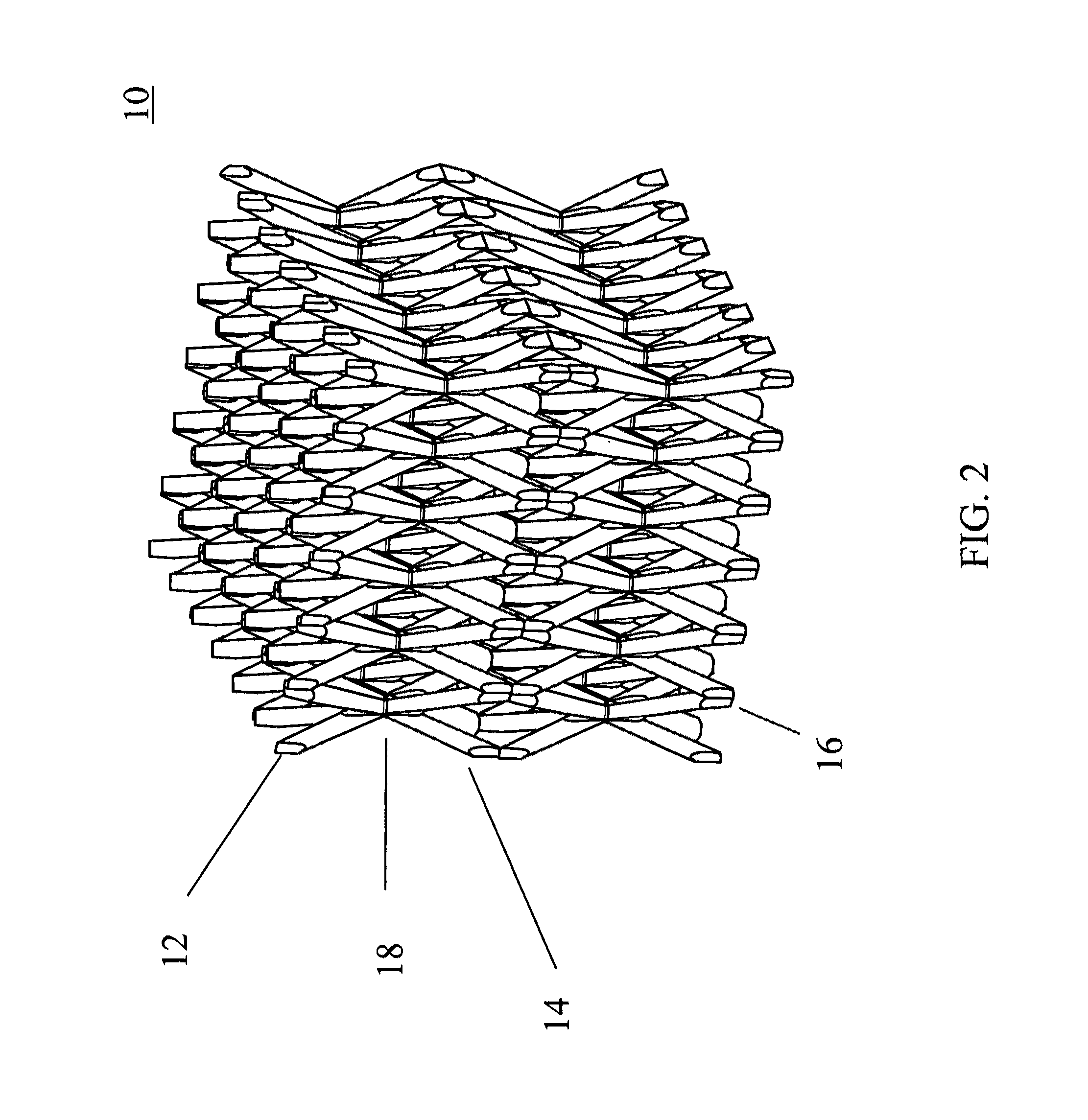
[0037]In the context of embodiments of the present invention, an ordered three-dimensional (3D) microstructure is referred to as an ordered 3D structure at the micrometer scale. An interface is referred as a boundary between two materials in physical contact, where the two materials may be suitably bounded (e.g., mechanically, electrically, or chemically bonded), and one side of the boundary is composed of the first material (or exclusively of the first material) and the other side of the boundary is composed of the second material (or exclus...


PUM

PropertyMeasurementUnit
Structureaaaaaaaaaa
Microstructureaaaaaaaaaa
Physical propertiesaaaaaaaaaa

Abstract

A three-dimensional (3D) composite structure and a method of making the same. In one embodiment, the 3D composite structure includes a 3D ordered microstructure and a second continuous material. The 3D ordered microstructure includes first truss elements defined by first self-propagating polymer waveguides and extending along a first direction, second truss elements defined by second self-propagating polymer waveguides and extending along a second direction, and third truss elements defined by third self-propagating polymer waveguides and extending along a third direction. The first, second, and third truss elements interpenetrate each other at nodes to form a first continuous material with the three-dimensional ordered microstructure. In addition, the second continuous material has different physical properties than the first continuous material and shares an interface with the three-dimensional ordered microstructure, and wherein the interface is everywhere continuous.

Description

FIELD OF THE INVENTION[0001]The present invention relates to a three-dimensional (3D) composite structure and a method of making the same.BACKGROUND OF THE INVENTION[0002]A composite material is composed of at least two distinct constituent materials or phases, that when combined have physical properties unlike the individual phases. The physical properties of a composite material are determined by the physical properties of the constituent materials, the volume or mass ratio of each phase, the interface properties between each of the phases, and the geometry of the phases. This invention disclosure is related to the relative geometry of the constituent phases.[0003]The constituent phases of a two-phase composite material are commonly termed for their mechanical function, i.e. reinforcement phase and matrix phase. The reinforcement phase provides the majority of the mechanical support while the matrix phase distributes the load between / to the reinforcement phase. Reinforcement mater...

Claims


Application Information

Patent Timeline
IPC IPC(8): G02B6/10E04B1/18B29D11/00B22F1/06
CPCB29D11/00663G02B6/12002G02B6/138Y02E60/14B22F1/06C04B38/0032F28D20/023
Inventor JACOBSEN, ALAN J.BARVOSA-CARTER, WILLIAM B.GROSS, ADAM F.CUMBERLAND, ROBERTKIRBY, KEVIN W.KISAILUS, DAVID
Owner HRL LAB
Why Eureka
Try Eureka