Kink resistant stent-graft

Inactive Publication Date: 2012-12-04
WL GORE & ASSOC INC
View PDF416 Cites 20 Cited by
  • Summary
  • Abstract
  • Description
  • Claims
  • Application Information

AI Technical Summary

Benefits of technology

[0018]With this construction, regions of the stent member do not interface with the coupling member. This is believed to advantageously reduce shear stresses between the stent member and the coupling member when the stent-graft undergoes bending so that tearing of the coupling and/or graft member can be minimized or eliminated. It is also believed that this arrangement minimizes the likelihood of delamination between the coupling member and the graft. If delamination were to occur, the inner portion of the stent-graft could perceivable collapse into the vessel lumen and interfere with desired blood flow. Thus, the stent-graft is believed to be capable of conforming to curves in a blood vessel lumen with minimal risk of tearing the graft or coupling member, or delamination between the stent and graft members.
[0019]According to another aspect of the invention, the coupling member is secured to the graft member without sutures. When the graft member is placed within the stent member, for example, this arrangement eliminates the need for having sutures extend into the lumen formed by the graft member and possibly interfere with blood flow. Another benefit of this arrangement, as compared to suturing the stent to the graft member, is that suture holes need not be placed in the graft which could adversely affect its integrity. The coupling member may be thermally or adhesively bonded to the graft member.
[0020]The coupling member preferably has a generally broad or flat working surface as compared to filament or thread-like structures such as sutures. As noted above, a preferred coupling member is in the form of a ribbon. This configuration advantageously increases potential bonding surface area between the coupling member and the graft member to enhance the integrity of the bond therebetween. The increased bonding surface may facilitate minimizing the thickness of the coupling member so that the stent-graft Patent lumen volume and blood flow dynamics therein can be optimized. For example, a thicker coupling member would increase the overall stent-graft thickness which can cause an undesirable lumen diameter reduction at the transition where the vessel lumen interfaces the inlet of the stent-graft. This, in

Problems solved by technology

If delamination were to occur, the inner portion of the stent-graft could perceivable collapse into the vessel lumen and interfere with desired blood flow.
For example, a thicker coupling member would increase the overall stent-graft thickness which

Method used


Image

  • Kink resistant stent-graft
  • Kink resistant stent-graft
  • Kink resistant stent-graft

Examples


Embodiment Construction

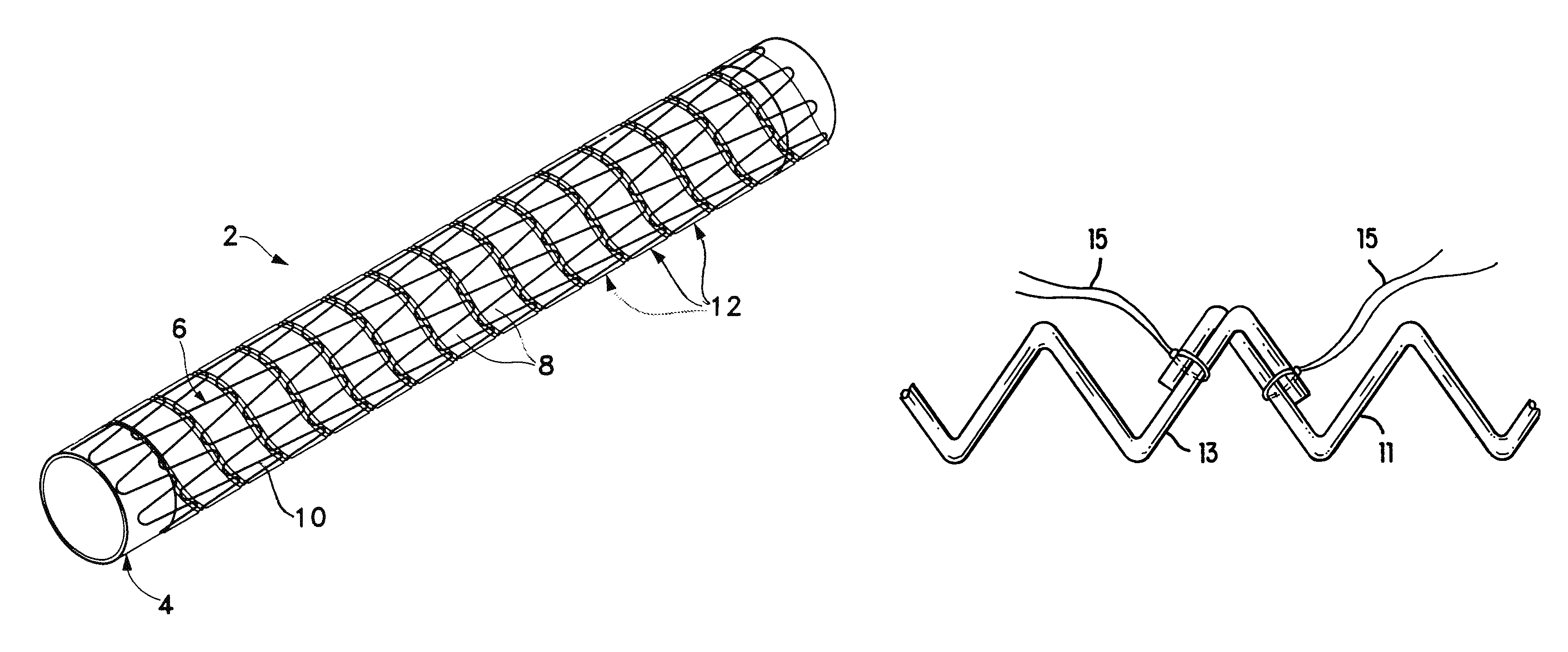
[0051]Referring to the drawings in detail wherein like numbers indicate like elements, an expandable stent-graft 2 is shown constructed according to the principles of the present invention. Although particular stent and graft constructions will be described in conjunction with the preferred embodiments, it should be understood that other constructions may be used without departing from the scope of the invention.

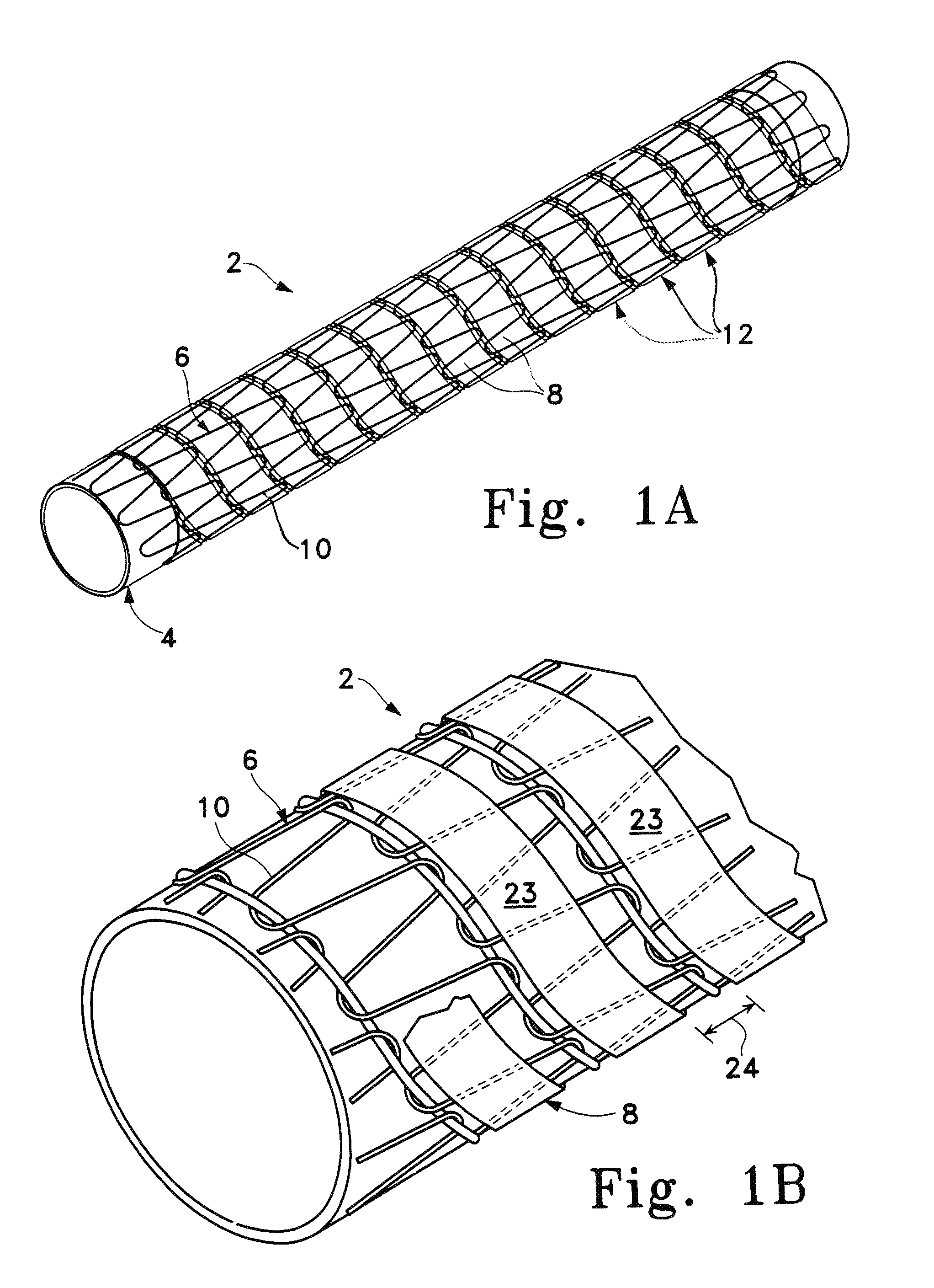
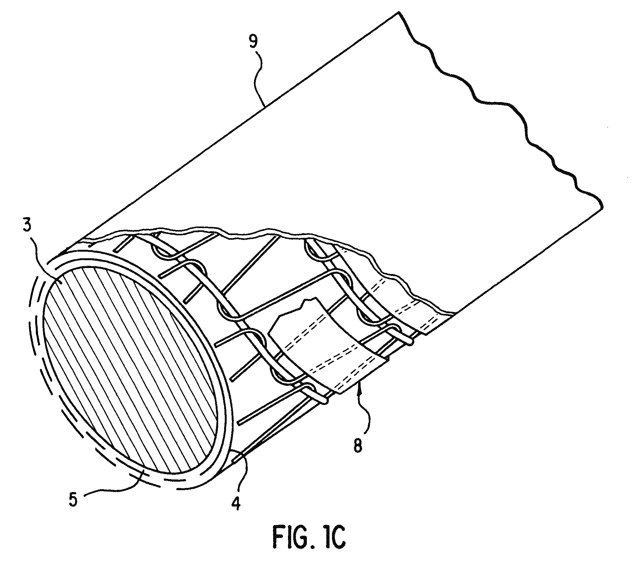
[0052]Referring to FIGS. 1A and B, stent-graft 2 generally includes a thin-walled tube or graft member 4, a stent member 6 and a coupling member 8 for coupling the stent and graft members together. Preferably, the stent and graft members are coupled together so that they are generally coaxial.

[0053]Tubular expandable stent member 6 is generally cylindrical and comprises a helically arranged undulating member 10 having plurality of helical turns 12 and preferably comprising nitinol wire. The undulations preferably are aligned so that they are “in-phase” with each other as sho...


PUM


Abstract

A stent-graft including a stent member having an inner surface and an outer surface, a generally tubular graft member and a coupling member that couples the stent member to the graft member. The coupling member, which is the preferred embodiment is in the form of a ribbon, covers only a portion of the inner or outer surface of the stent member and secures the stent member and graft member to one another. Alternatively, the coupling member can be described as interconnecting less than entirely the inner or outer surface of the graft member to the stent member. With this construction, regions of the stent member do not interfere with the coupling member. Shear stresses between the stent member and the coupling member and the risk of tearing the graft or coupling member or delamination therebetween may be reduced as compared to a fully enveloped stent member. This construction also provides improved flexibility and kink resistance.

Description

CROSS-REFERENCE TO RELATED APPLICATIONS[0001]This application is a continuation application under 37 C.F.R. §1.53(b) of U.S. patent application Ser. No. 09 / 888,499 filed Jun. 26, 2001 (now U.S. Pat. No. 6,520,986 issued Feb. 18, 2003), which is a divisional application of U.S. application Ser. No. 09 / 376,931 filed Aug. 13, 1999 (now U.S. Pat. Ser. No. 6,361,637 issued Mar. 26, 2002), which is a divisional application of U.S. patent application Ser. No. 08 / 896,805 filed Jul. 18, 1997 (now U.S. Pat. Ser. No. 6,042,605 issued Mar. 28, 2000), which is a continuation-in-part application of U.S. patent application Ser. No. 08 / 572,548 filed on Dec. 14, 1995 (now abandoned).FIELD OF THE INVENTION[0002]This invention relates generally to implants for repairing ducts and passageways in the body. More specifically, the invention relates to an expandable stent-graft.CONTINUING DATA[0003]This is a continuation-in-part of prior application Ser. No. 08 / 572,548, filed Dec. 14, 1995, the entirety of...

Claims


Application Information

Patent Timeline
IPC IPC(8): A61F2/06A61F2/00A61F2/88A61F2/90
CPCA61F2/07A61F2/88A61F2/95A61F2/844A61F2230/0041A61F2/90A61F2002/075A61F2002/9511A61F2002/9665A61F2210/0019A61F2250/0098A61F2/89A61F2220/0091A61F2230/0078A61F2220/0075A61F2230/006
Inventor MARTIN, GERALD RAYLAU, LILIPSTONEBROOK, SCOTT N.LAM, SHARONTHORNTON, TROY
Owner WL GORE & ASSOC INC
Why Eureka
Try Eureka