Composite ferrite sheet, method of fabricating the composite ferrite sheet, and array of sintered ferrite segments used to form the composite ferrite sheet

a technology of composite ferrite and ferrite, which is applied in the field of composite ferrite, can solve the problems of natural rupture of sintered green sheets, and achieve the effects of improving productivity, high degree of accuracy of depth, and effective improvement of productivity of grooved ferrite green sheets

Active Publication Date: 2012-12-04
MARUWA
View PDF21 Cites 2 Cited by
  • Summary
  • Abstract
  • Description
  • Claims
  • Application Information

AI Technical Summary

Benefits of technology

[0010]In view of the related art described above, the present inventor made an intensive study of the manner of effectively improving the productivity of a grooved ferrite green sheet and the accuracy of depth of dividing grooves formed in the grooved ferrite sheet (sintered body) used to form the planar ferrite layer of the laminated composite ferrite sheet, which includes at least the planer ferrite layer and the sheet layers supporting the planar ferrite layer, as described above. As a result of the study, the inventor conceived the utilization of a groove forming die 100 shown in FIG. 23, to form dividing grooves in a ceramic sheet which gives a resistor in the form of a chip. This groove forming die 100 has longitudinal groove forming blades 104 and transverse groove forming blades 106 which have a triangular cross sectional shape and which are formed in a grid pattern so as to protrude from a back surface (lower surface) of a substrate 102 which is to be brought into pressing contact with the ceramic sheet to form the dividing grooves. The inventor conceived the use of this groove forming die 100 to form the grooved green sheet in the fabrication of the composite ferrite sheet of the present invention. The use of this groove forming die 100 permits simultaneous formation of a multiplicity of longitudinal grooves 112 and a multiplicity of transverse grooves 114 that have substantially V-shaped cross section having a desired depth, in a surface of a green sheet 110 having a desired thickness, as shown in FIG. 24, by one-shot operation to press the groove forming die 100 onto the above-indicated surface of the green sheet 110. Thus, the inventor recognized an effective improvement of the accuracy of the depth of the dividing grooves and a considerable improvement of the efficiency of formation of the dividing grooves.
[0013]It is therefore a first object of the present invention to provide a method of fabricating a composite ferrite sheet with effectively improved quality and productivity, by fabricating a grooved ferrite sheet which can be easily handled in the method of firing a grooved ferrite green sheet and in the processes preceding and following the firing process, even where the thickness of the grooved ferrite green sheet is relatively small. It is a second object of the invention to provide a composite ferrite sheet having excellent properties. It is a third object of the invention to provide an array of sintered ferrite segments which constitutes the composite ferrite sheet and which has excellent properties.
[0030]In the method of fabricating the composite ferrite sheet in accordance with the present invention, the first grooves and the second grooves can be formed in a grid pattern in the ferrite green sheet at one time with a high degree of accuracy of their depth, by simply pressing the groove forming die having the specifically configured first and second protrusions onto one of the opposite major surfaces of the ferrite green sheet. Thus, the productivity of the grooved ferrite green sheet is effectively improved, and the desired composite ferrite sheet can be advantageously fabricated with improved productivity.
[0031]Further, the grooved ferrite green sheet formed by using the groove forming die having the specifically configured first and second protrusions in accordance with the present invention is provided with the first and second grooves which have the triangular cross sectional shape and which cooperate with each other to form the grid pattern in which each groove of at least one of those two kinds of grooves is discontinuous at each imaginary intersecting portion of the first and second grooves, namely, is divided into a plurality of divisions which are spaced apart from each other in the extending direction of the groove at the imaginary intersecting portion. Accordingly, unlike an intersecting portion of two kinds of grooves formed in the conventional grid pattern, the imaginary intersecting portion of the grooved ferrite green sheet is not provided with a groove formed in the direction of thickness of the grooved ferrite green sheet, so that the grooved ferrite green sheet is reinforced in its direction of thickness by the imaginary intersecting portions. As a result, the ease of handling of the grooved green sheet is advantageously improved, and the ease of handling of the sintered ferrite sheet obtained by firing the grooved ferrite green sheet is effectively improved, making it possible to effectively prevent a problem of natural rupture of the sintered ferrite sheet.
[0032]Where all of the grooves of both of the two kinds of grooves formed in the grid pattern are discontinuous at the imaginary intersecting portions of the two kinds of grooves, namely, where each groove of the two kinds of grooves is divided into a plurality of divisions which are spaced apart from each other at each imaginary intersecting portion, the grooved ferrite green sheet can be further reinforced, and recesses can be formed independently of the grooves, at the respective imaginary intersecting portions, by respective protrusions formed on the groove forming die, which are means for forming rupture assisting portions, so that those recesses permit easier rupturing of the sintered ferrite sheet obtained by firing the grooved ferrite green sheet, such that the sintered ferrite sheet is more accurately ruptured along the dividing grooves formed therein.
[0033]Furthermore, at least one side face of the multiplicity of sintered ferrite segments obtained by rupturing the sintered ferrite sheet to obtain the composite ferrite sheet of the invention has at least one ruptured section that is ruptured over an entire thickness of the sintered ferrite segment at least one end portion in an extending direction of one of the first dividing groove and the second dividing groove (except for a portion corresponding to the rupture assisting portion if provided at each imaginary intersecting portion). Thus, a planar ferrite layer is advantageously formed by butting the multiplicity of sintered ferrite segments in the two mutually perpendicular directions so as to be arranged in a grid pattern. In addition, unlike a composite ferrite sheet having sintered ferrite segments obtained from a sintered ferrite sheet having two kinds of continuous dividing grooves, the present composite ferrite sheet has a smaller surface area of a gap between the opposite side faces of the adjacent two sintered ferrite segments, so that the present composite ferrite sheet is accordingly protected against reduction of effective magnetic permeability caused by flux leakage, and deterioration of its rupturing characteristics in the bending step.

Problems solved by technology

In addition, the sintered green sheet may have natural rupture in the firing process.

Method used


Image

  • Composite ferrite sheet, method of fabricating the composite ferrite sheet, and array of sintered ferrite segments used to form the composite ferrite sheet
  • Composite ferrite sheet, method of fabricating the composite ferrite sheet, and array of sintered ferrite segments used to form the composite ferrite sheet
  • Composite ferrite sheet, method of fabricating the composite ferrite sheet, and array of sintered ferrite segments used to form the composite ferrite sheet

Examples


Embodiment Construction

[0059]To further clarify the present invention, one typical embodiment of this invention will be described in detail by reference to the drawings.

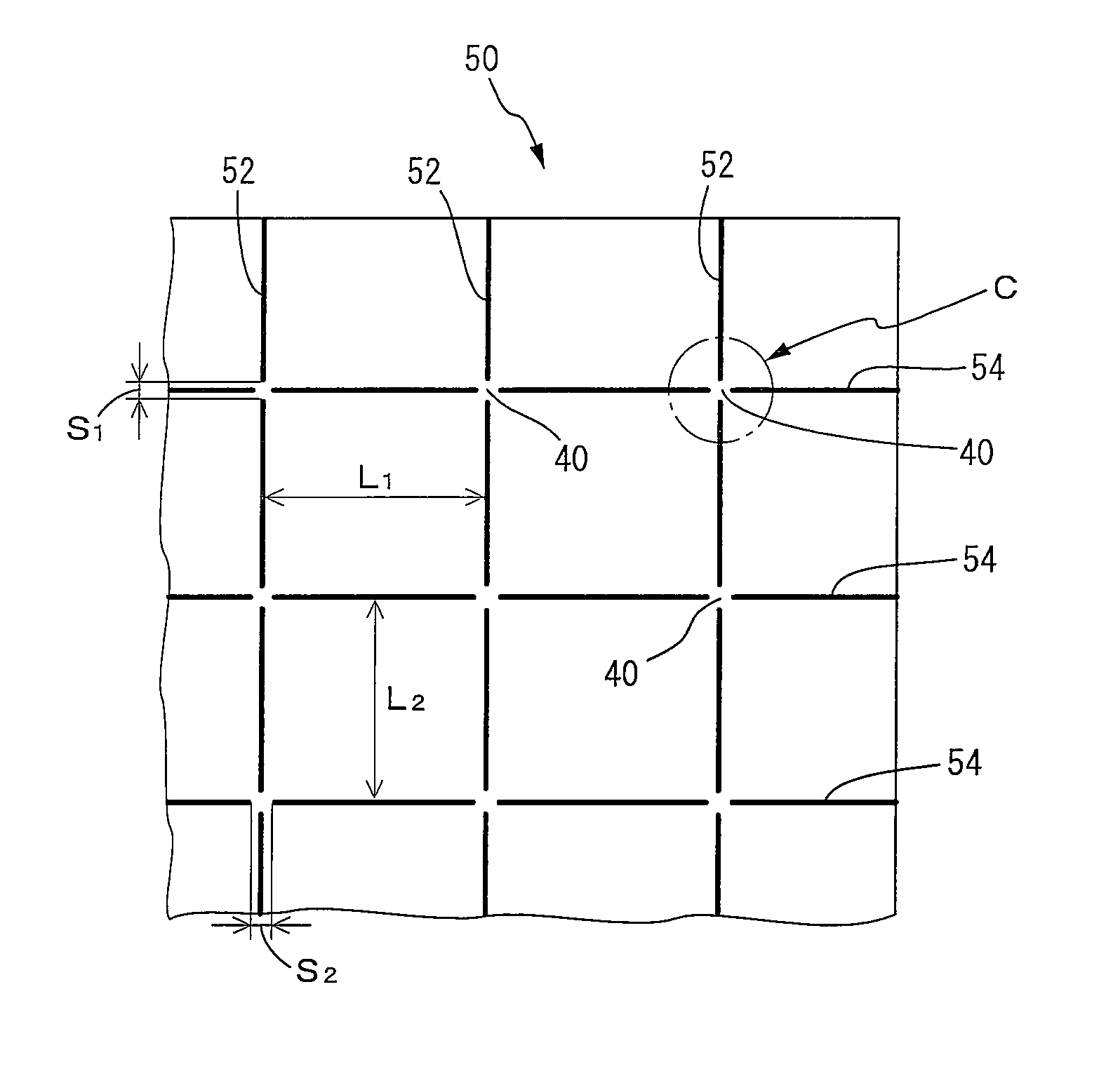
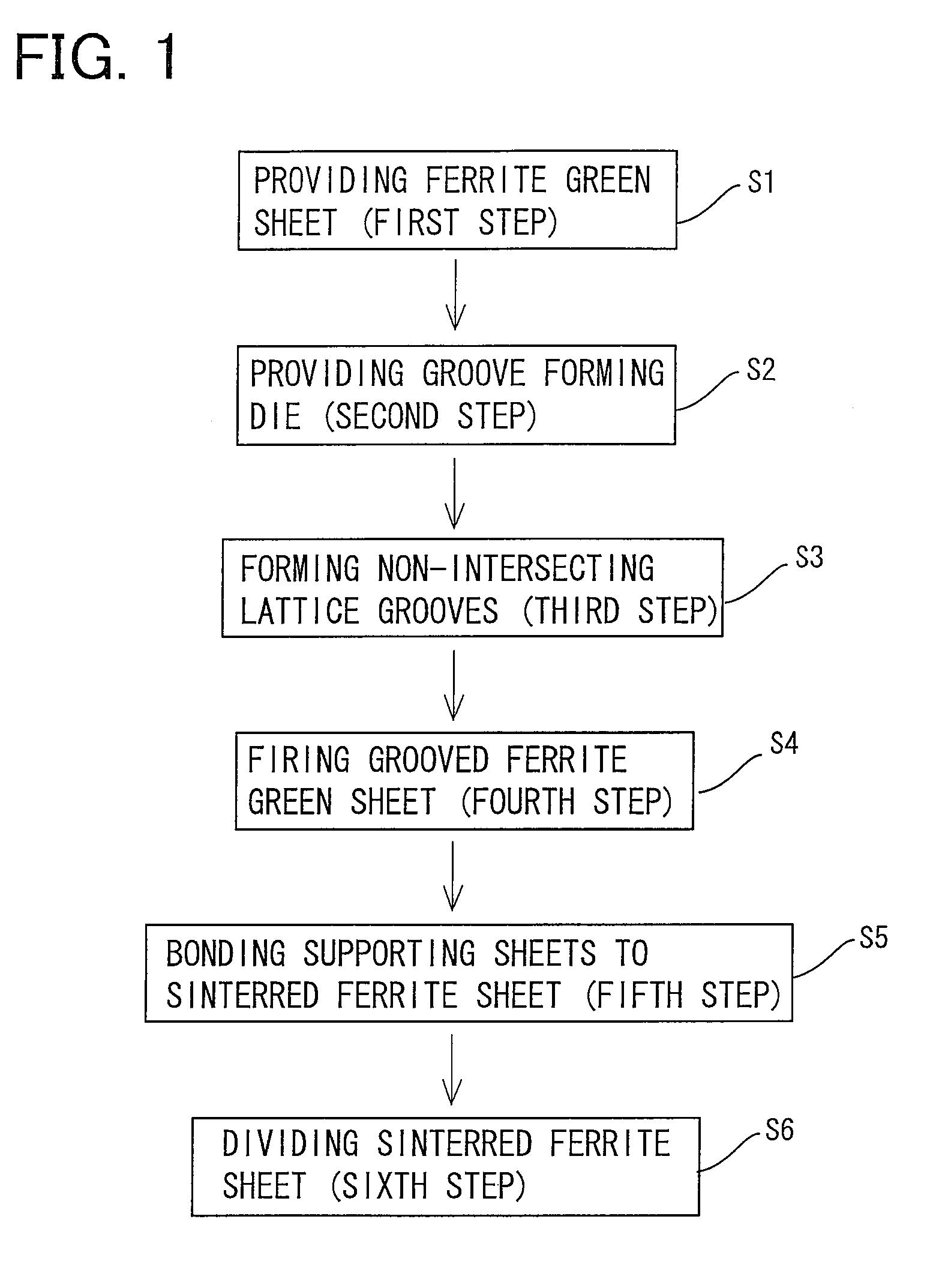
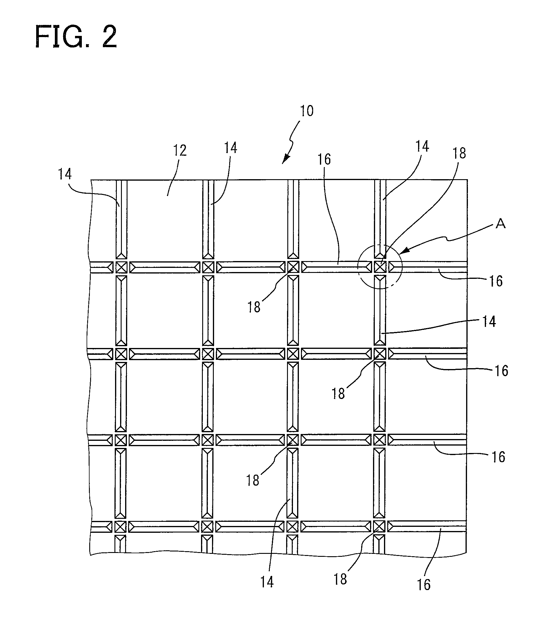
[0060]Referring first to FIG. 1, there are shown steps of a method of fabricating a composite ferrite sheet of this invention. Namely, the composite ferrite sheet is fabricated by the process including a first step S1 of providing a ferrite green sheet, a second step S2 of providing a groove forming die having two kinds of protrusions which have a triangular cross sectional shape and which are arranged in a non-intersecting grid pattern, a third step S3 of forming a grooved ferrite green sheet having two kinds of non-intersecting V-shaped grooves, a fourth step S4 of firing the grooved ferrite green sheet to obtain a sintered ferrite sheet, a fifth step S5 of bonding supporting sheets to the sintered ferrite sheet, to obtain a laminated ferrite sheet, and a sixth step S6 of bending the laminated ferrite sheet so as to divide the sintered f...


PUM

PropertyMeasurementUnit
thicknessaaaaaaaaaa
thicknessaaaaaaaaaa
temperatureaaaaaaaaaa

Abstract

A method of fabricating a composite ferrite sheet including the steps of: (a) forming a grooved green ferrite sheet having a non-intersecting grid pattern by pressing a groove forming die including a plurality of first protrusions and a plurality of second protrusions having a triangular cross sectional shape, each protrusion of at least one of the plurality of first protrusions and the plurality of second protrusions being discontinuous at each imaginary intersecting portion at which extension lines of the respective first and second protrusions intersect each other, (b) firing the grooved ferrite green sheet to obtain a sintered ferrite sheet, (c) bonding at least one supporting sheet to at least one of opposite major surfaces of the sintered ferrite sheet, and (d) rupturing the sintered ferrite sheet along the grooves into a multiplicity of separate and independent rectangular planar ferrite segments which are bonded to the supporting sheet.

Description

[0001]The present application is based on Japanese Patent Applications No. 2011-086103 filed on Apr. 8, 2011 and No. 2011-234355 filed on Oct. 25, 2011, the contents of which are incorporated herein by reference.BACKGROUND OF THE INVENTION[0002]1. Field of the Invention[0003]The present invention relates in general to a composite ferrite sheet, a method of fabricating the composite ferrite sheet, and an array of sintered ferrite segments used for the composite ferrite sheet, and more particularly to a method of advantageously fabricating a flexible composite ferrite sheet which has a planar sintered ferrite layer divided into rectangular segments and which absorbs or blocks external electromagnetic waves incident upon electronic components or electromagnetic waves generated by the electronic components per se, or which is bonded to NFC devices or antenna coils to improve their communication performance or improve performance of non-contact type power transmission devices, and a meth...

Claims


Application Information

Patent Timeline
Patent Type & Authority Patents(United States)
IPC IPC(8): B32B3/30
CPCC04B35/26C04B35/2633C04B35/265C04B35/2658C04B35/2691C04B35/2666Y10T428/24355Y10T428/2457Y10T428/24612B32B9/00H01F1/34H05K9/00
Inventor NISHI, IKUO
Owner MARUWA
Why Eureka
Try Eureka