
Micromachined patch-clamp apparatus

a micromachined and patch-clamp technology, applied in the field of micromachined apparatus, can solve the problem of tedious conventional use of patch-clamp techniqu

Active Publication Date: 2012-12-04
NAT TECH & ENG SOLUTIONS OF SANDIA LLC
View PDF22 Cites 11 Cited by
  • Summary
  • Abstract
  • Description
  • Claims
  • Application Information

AI Technical Summary

Problems solved by technology

This conventional use of the patch-clamp technique is tedious and allows the analysis of only a few cells per day.

Method used


Image

  • Micromachined patch-clamp apparatus
  • Micromachined patch-clamp apparatus
  • Micromachined patch-clamp apparatus

Examples


first embodiment

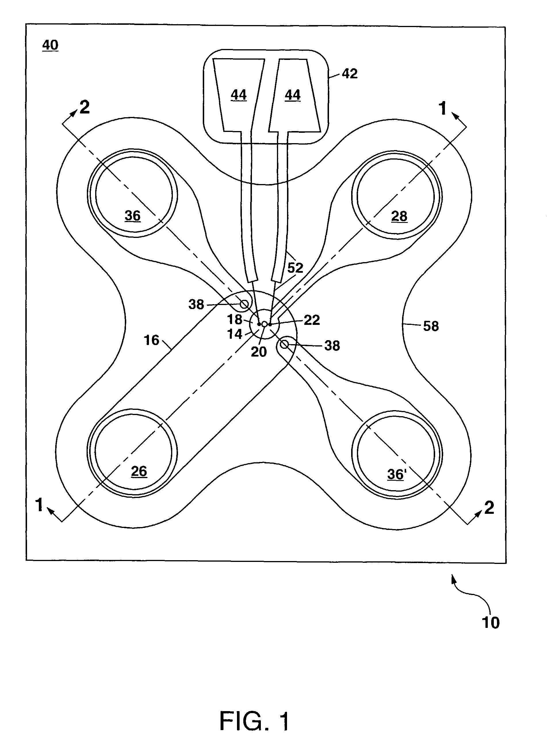
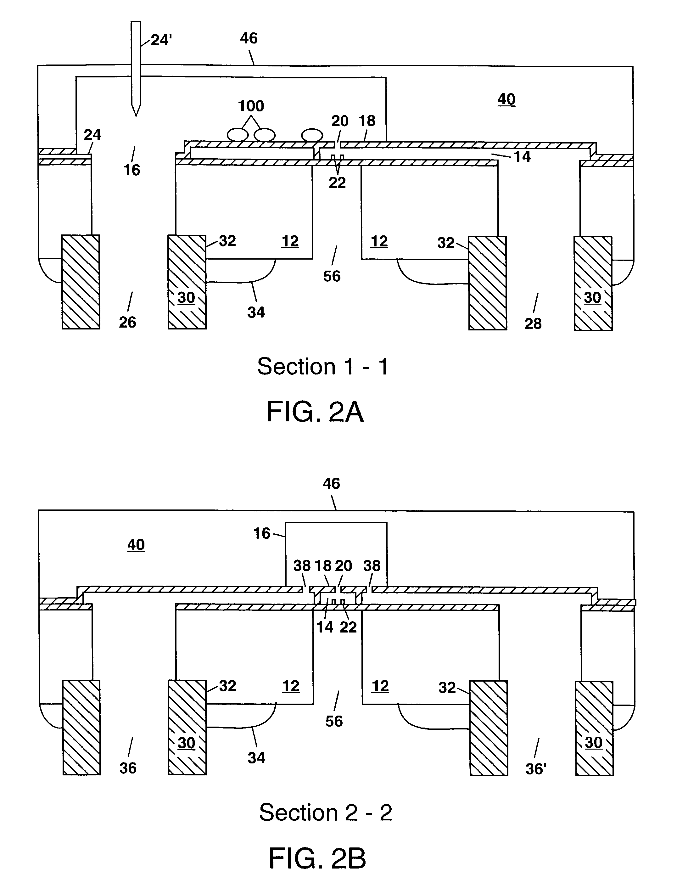
[0025]FIGS. 1 and 2A, 2B schematically illustrate in plan view and cross-section views, respectively, the patch-clamp apparatus 10 of the present invention. The apparatus 10 in FIGS. 1 and 2A, 2b comprises a silicon substrate 12, with a pair of fluid chambers being formed above the substrate 12, including a lower chamber 14 and an upper chamber 16 separated by a common wall 18 which preferably comprises silicon nitride and which is oriented parallel to the plane of the substrate 12. The common wall 18 includes an opening 20 between the lower and upper chambers, 14 and 16, with the opening 20 being smaller than the cells 100 being analyzed. Generally, the opening 20 is micron-sized (e.g. 1-10 μm across).

[0026]The opening 20 is used to localize the cell membrane and to provide a high-resistance seal to the cell 100 so that electrical connections can be made to measure minute (nanoampere to picoampere) electrical currents that flow through the cell membrane (i.e. through ion channels t...

third embodiment

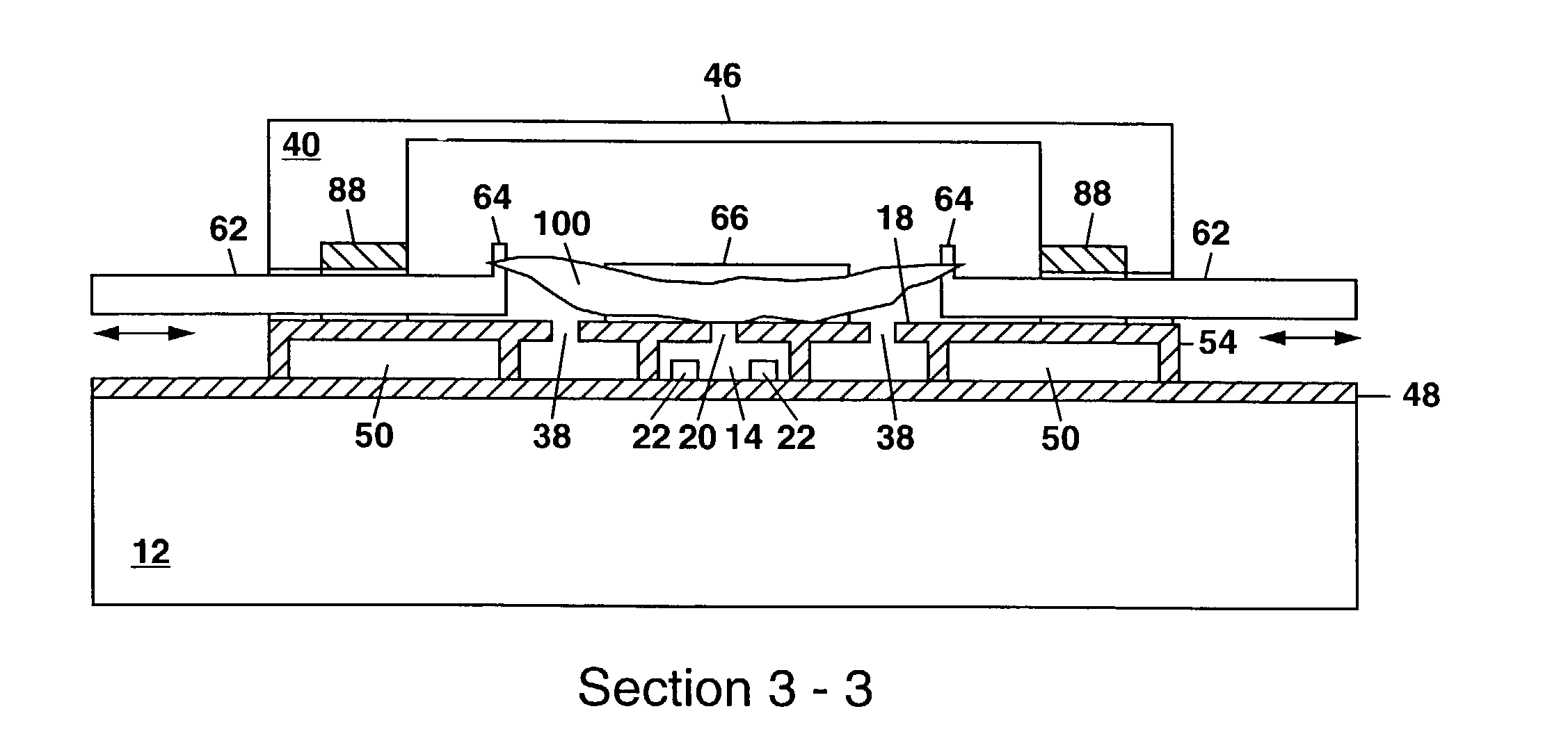
[0050]FIG. 6 shows a schematic plan view of the micromachined patch-clamp apparatus 10 of the present invention. In FIG. 6, the molded polymer material 40 has been omitted for clarity although this material 40 is shown in the cross section view of FIG. 7 along the section line 3-3 in FIG. 6.

[0051]The apparatus 10 in FIG. 6 includes a plurality of additional layers of deposited and patterned polysilicon that are used to form one or more electrostatic actuators 60 on the substrate 12. The electrostatic actuators 60 can be operatively connected to a biological cell 100 (e.g. an elongate muscle cell) to provide mechanical stimulation to the cell 100 during analysis with the patch-clamp technique. Each electrostatic actuator 60 can be mechanically coupled through a linkage 62 formed from the additional polysilicon layers, with the linkage 62 being terminated by one or more attachment points 64 (e.g. in the form of upward-extending posts) that can be used to form an attachment to a biolog...


PUM

PropertyMeasurementUnit
sizeaaaaaaaaaa
sizeaaaaaaaaaa
sizeaaaaaaaaaa

Abstract

A micromachined patch-clamp apparatus is disclosed for holding one or more cells and providing electrical, chemical, or mechanical stimulation to the cells during analysis with the patch-clamp technique for studying ion channels in cell membranes. The apparatus formed on a silicon substrate utilizes a lower chamber formed from silicon nitride using surface micromachining and an upper chamber formed from a molded polymer material. An opening in a common wall between the chambers is used to trap and hold a cell for analysis using the patch-clamp technique with sensing electrodes on each side of the cell. Some embodiments of the present invention utilize one or more electrostatic actuators formed on the substrate to provide mechanical stimulation to the cell being analyzed, or to provide information about mechanical movement of the cell in response to electrical or chemical stimulation.

Description

GOVERNMENT RIGHTS[0001]This invention was made with Government support under Contract No. DE-AC04-94AL85000 awarded by the U.S. Department of Energy. The Government has certain rights in the invention.CROSS REFERENCE TO RELATED INVENTIONS[0002]This patent application is related to co-pending patent application Ser. No. 09 / 779,164 which is incorporated herein by reference.FIELD OF THE INVENTION[0003]The present invention relates generally to devices for studying or analyzing biological cells, and in particular to a micromachined apparatus for holding one or more biological cells to allow electrophysiological evaluations thereof based on the patch-clamp technique.BACKGROUND OF THE INVENTION[0004]The patch-clamp technique was originally developed to study cell membrane electrophysiology by measuring very small (10−9-10−12 A) electrical currents that can flow through ion channels embedded in the lipid bilayers that form cell membranes. Such ion channels, which are typically made of prot...

Claims


Application Information

Patent Timeline
Patent Type & Authority Patents(United States)
IPC IPC(8): C12M1/42C12M3/00C12N13/00
CPCC12N13/00G01N33/48728
Inventor OKANDAN, MURAT
Owner NAT TECH & ENG SOLUTIONS OF SANDIA LLC
Learn More