Nucleate boiling cooling system

a cooling system and nuclear technology, applied in the direction of machines/engines, mechanical devices, cylinders, etc., can solve the problems of uncontrolled boiling in the coolant passages of the engine, complete partial loss of liquid to metal contact, etc., to achieve the effect of increasing the heat flux

Active Publication Date: 2012-12-11
DEERE & CO
View PDF22 Cites 7 Cited by
  • Summary
  • Abstract
  • Description
  • Claims
  • Application Information

AI Technical Summary

Problems solved by technology

One of the principle sources of parasitic losses, complications and bulk in an internal combustion engine has to do with the waste heat generated by the internal combustion engine process.
When cooling systems operate under off design conditions because of duty cycle or component malfunction, it can lead to a condition of uncontrolled boiling in the coolant passages for the engine.
This condition causes complete loss of liquid to metal contact and drastically reduces the heat flux carried away by the cooling system.
This, in turn, has a potentially catastrophic affect on the temperature of the internal metal parts of the engine.
There is, however, a condition between normal liquid flow conditions and uncontrolled boiling that provides an optimum heat flux from the parts to be cooled by the liquid cooling system.
This allows significant increases in heat flux, but this condition, at best, is a momentary transition between sub-boiling conditions and uncontrolled or macro-boiling.
Such a system, while effective in maintaining conditions of nucleate boiling, has additional complications and complexity which increases the cost of such a system for an internal combustion system.

Method used


Image

  • Nucleate boiling cooling system
  • Nucleate boiling cooling system

Examples


Embodiment Construction

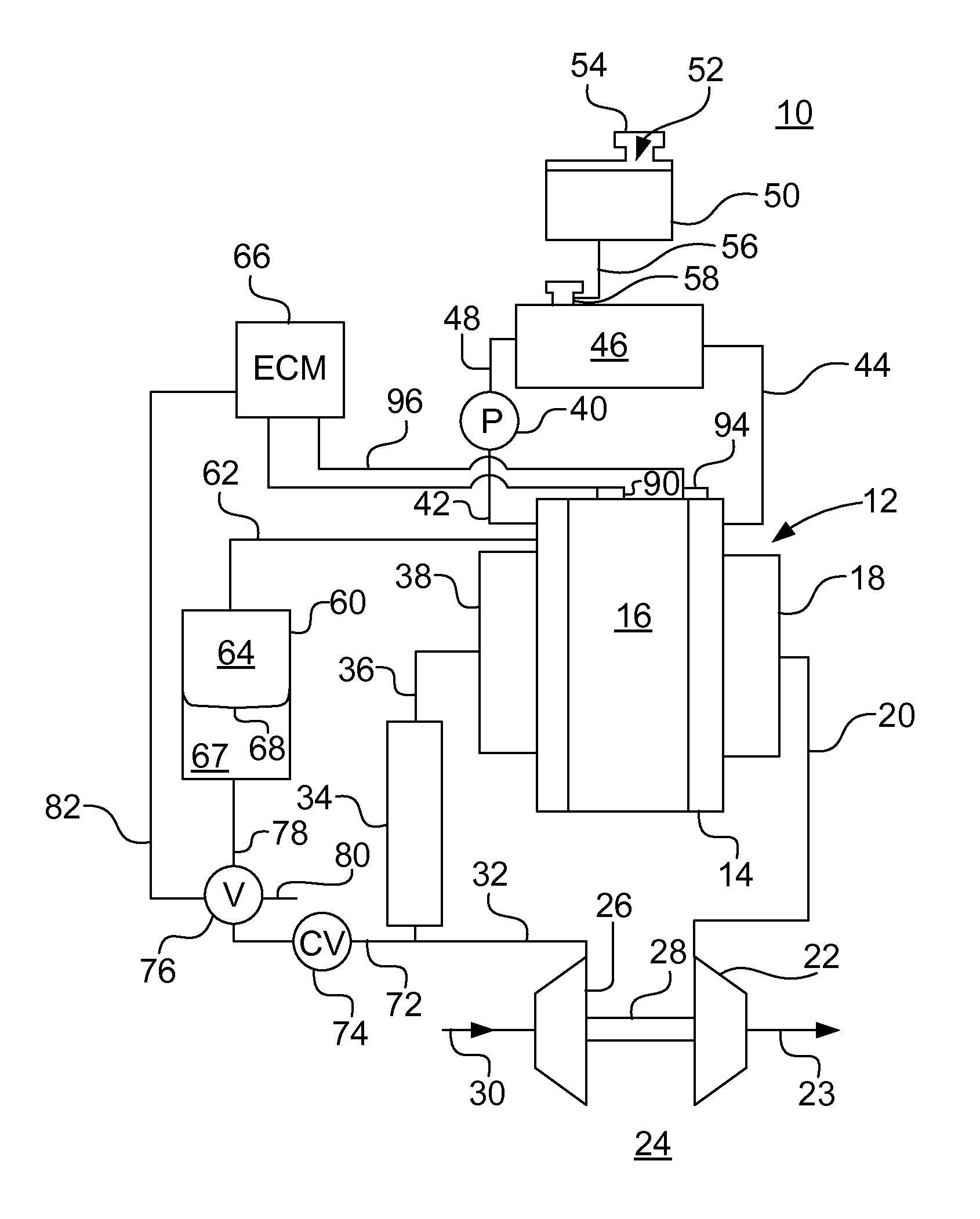
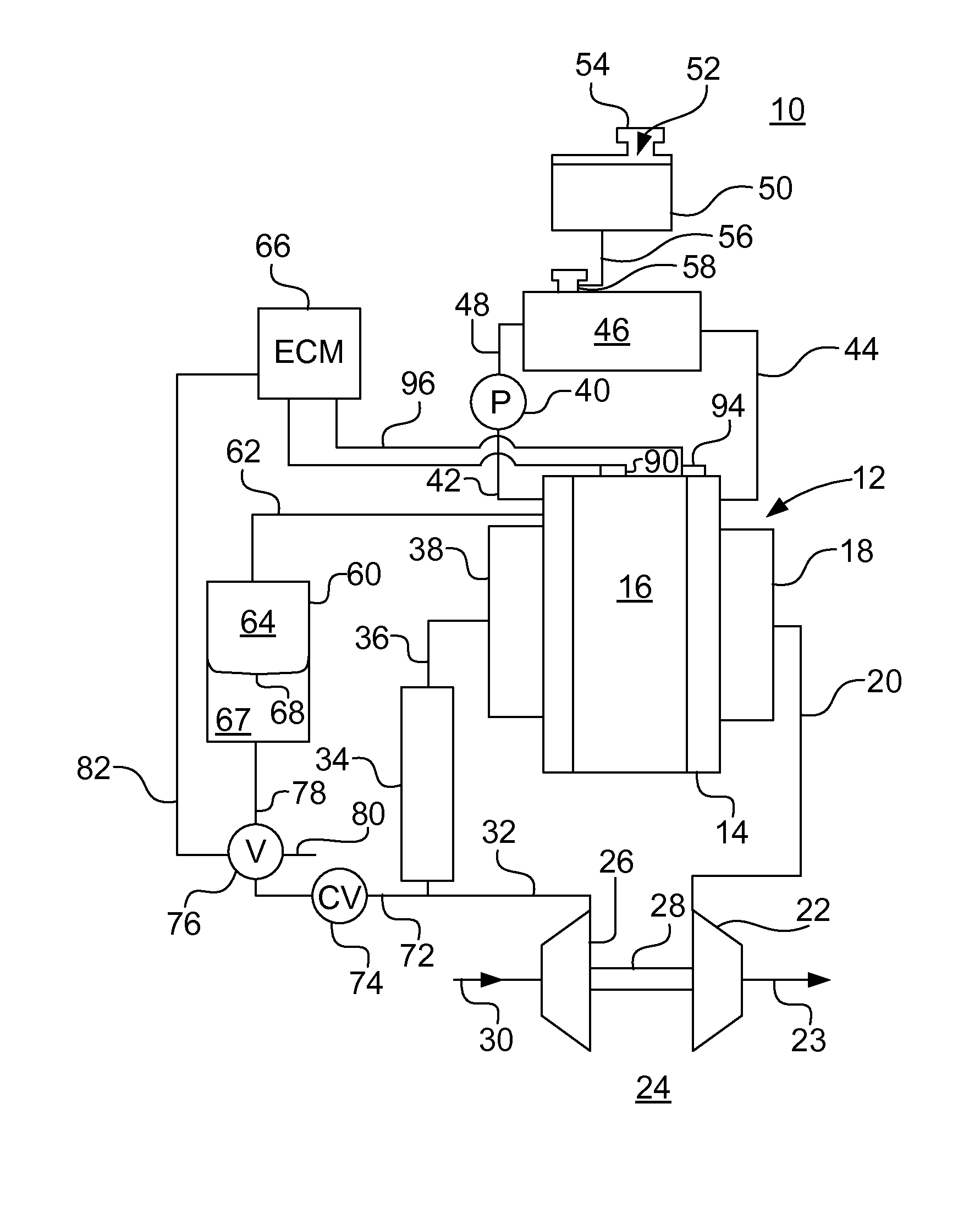
[0009]Referring to FIG. 1, there is shown a power system 10 having an internal combustion engine, generally indicated by reference character 12. Internal combustion engine 12 may be one of a number of types of engines in terms of combustion process but is usually a liquid cooled internal combustion engine 12 having a block 14 and a head 16, both of which have internal surfaces exposed to a combustion chamber of variable volume provided by reciprocating pistons all connected to an output crankshaft to provide a rotary power output. Details of the internal portions of block 14 and head 16 are not shown to simplify the understanding of the present invention. Engine 12 has an exhaust manifold 18 receiving products of combustion and delivering them through an exhaust conduit 20 to a turbine 22 of a turbocharger 24 and ultimately to an exhaust conduit 23 leading to ambient. The turbine 22 drives a compressor 26 through a common shaft 28. The compressor 26 receives ambient air from an inle...


PUM


Abstract

A cooling system for a liquid cooled internal combustion engine having coolant passages and a heat exchanger selected to operate the engine cooling system in the region of nucleate boiling. A sensor detects the presence of nucleate boiling and a variable volume chamber has a flexible diaphragm urged on one side by controlled air pressure and responsive to the sensor maintain the coolant system pressure at a level maintaining optimum nucleate boiling to increase heat flux from the engine and reduce overall size of the system.

Description

FIELD OF THE INVENTION[0001]The present invention relates to internal combustion engine systems and more specifically to coolant systems and methods for such systems.BACKGROUND OF THE INVENTION[0002]One of the principle sources of parasitic losses, complications and bulk in an internal combustion engine has to do with the waste heat generated by the internal combustion engine process. Attempts have been made to manage heat flux from the material surrounding combustion chambers by paying careful attention to flow passages, coolant flow rates and temperatures through such passages. Typically, internal combustion engines are liquid cooled so as to maximize the heat flux to the cooling system, particularly in the region closely adjacent the combustion chamber. When cooling systems operate under off design conditions because of duty cycle or component malfunction, it can lead to a condition of uncontrolled boiling in the coolant passages for the engine. This condition causes complete los...

Claims


Application Information

Patent Timeline
Patent Type & Authority Patents(United States)
IPC IPC(8): F01P3/22
CPCF01P9/00F01P2025/04
Inventor VUK, CARL T.
Owner DEERE & CO
Why Eureka
Try Eureka