Gas combustion type driving tool

a technology of driving tool and combustion type, which is applied in the field of improving the structure of the combustion chamber of the combustion type driving tool, can solve the problems of unsuitable corner driving operation, difficult handling of the driving tool, and heavy weight of the driving tool, and achieves the effect of reducing the total height, sufficient driving capability, and small siz

Active Publication Date: 2012-12-11
MAX CO LTD
View PDF23 Cites 0 Cited by
  • Summary
  • Abstract
  • Description
  • Claims
  • Application Information

AI Technical Summary

Benefits of technology

[0009]One or more embodiments of the invention relate to a gas combustion type driving tool that can realize a small size by reducing a total height while securing a predetermined volume in a combustion chamber, with a basic arrangement structure maintained, and have a sufficient driving capability without impairing a usability in carrying out a corner driving operation.
[0013]According to the first aspect, the movable sleeve is larger in diameter than the cylinder, with the lower end of the movable sleeve extending below the upper open end of the cylinder, and the annular sliding portion for sliding with the opening portion at the lower end of the movable sleeve is formed on the outer circumference of the cylinder and below the upper opening end, whereby the combustion chamber is formed not only on an upper portion of the cylinder but also extends around the cylinder. The height of the movable sleeve can be reduced by an increased volume around the cylinder. Accordingly, it is possible to provide a gas combustion type driving tool that can reduce the total height while securing a predetermined volume in the combustion chamber with a basic arrangement structure maintained, and have a sufficient driving capability without impairing the usability in carrying out the corner driving operation.
[0014]According to the second aspect, since the sliding portion of the cylinder is formed below the top dead center of the piston slidably accommodated in the cylinder, it is possible to extend the combustion chamber around the cylinder and reduce the height of the movable sleeve by an increased volume around the cylinder as in the first aspect.
[0015]According to the third aspect, since the cylindrical partition wall portion is provided on the extension from the upper end of the cylinder, and the opening portion is formed on each of the upper part and the lower part of the partition wall portion, a flow path leading from the central part of the combustion chamber through the lower opening portion to a lower portion of the combustion chamber outside the partition wall portion and further from a lower portion to an upper portion of the combustion chamber outside, from an upper portion of the combustion chamber outside through the upper opening portion to the central part of the combustion chamber is formed inside the combustion chamber. Therefore, when the fuel gas and the air supplied into the combustion chamber are agitated and mixed, the mixed gas flows smoothly along the flow path without residing, whereby the agitation and mixture efficiency is excellent to burn the mixed gas securely.

Problems solved by technology

However, the driving tool with great total height has a problem that the tool is not only heavy and tiring, but also less convenient during carrying out a corner driving operation or an oblique driving operation because the upper part is an obstacle.
Besides, though there is a possible solution for increasing the diameter of the movable sleeve to suppress the height of the combustion chamber, the body of the driving tool is thickened even though the total height can be suppressed, whereby the tool is difficult to handle and is unsuitable for carrying out the corner driving operation.

Method used


Image

  • Gas combustion type driving tool
  • Gas combustion type driving tool
  • Gas combustion type driving tool

Examples


Embodiment Construction

[0030]A nailing machine will be described as an exemplary embodiment of a gas combustion type driving tool according to the present invention.

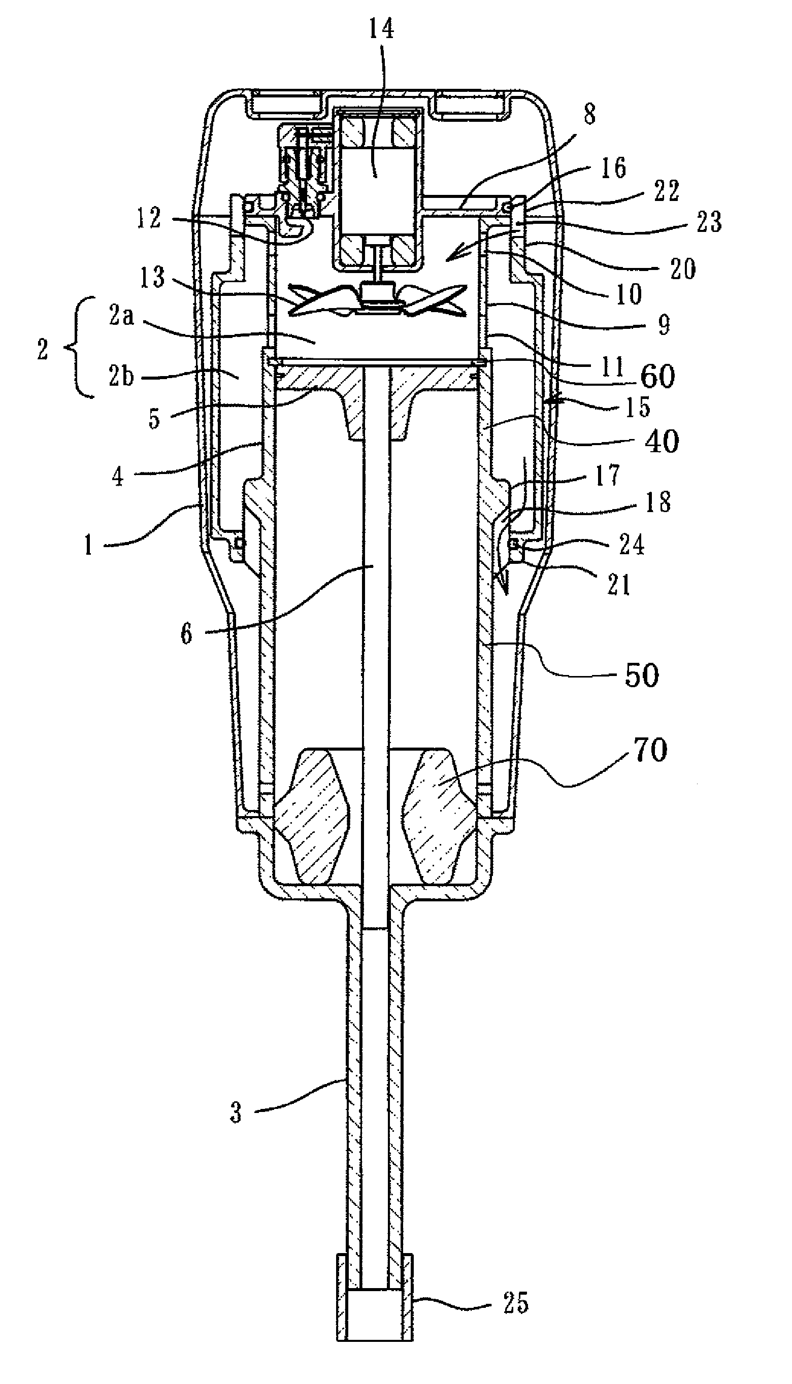
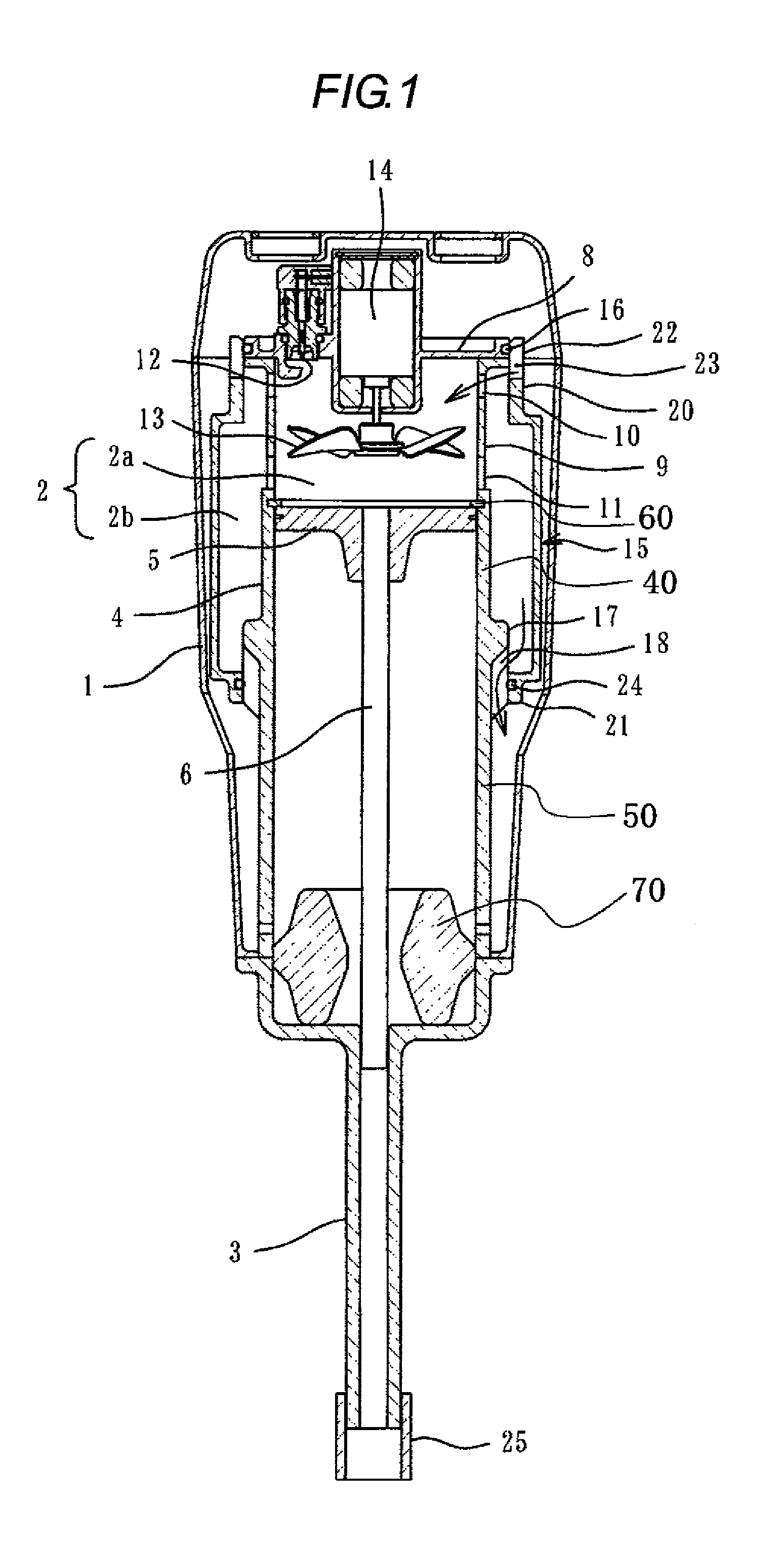
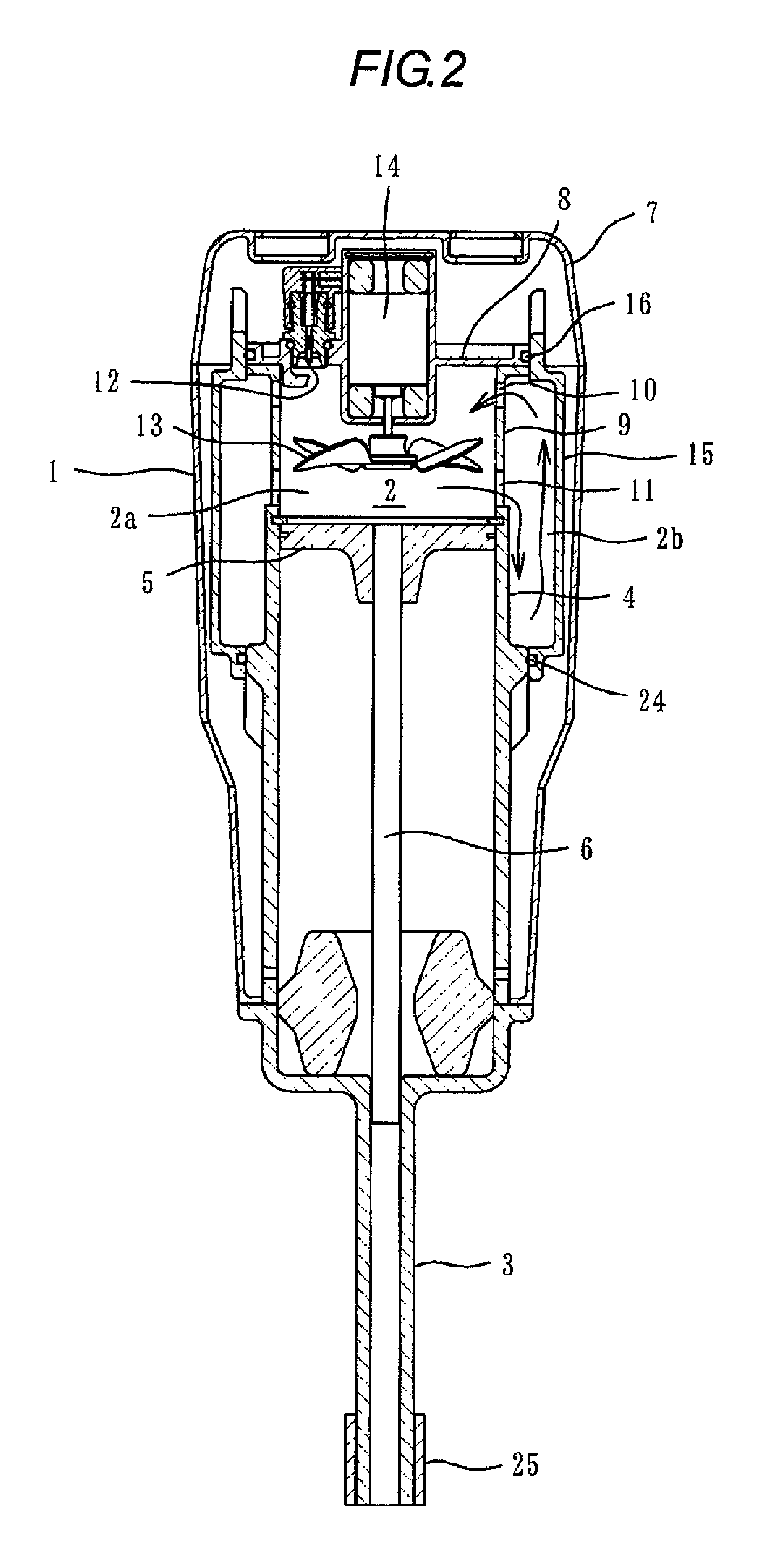
[0031]In FIGS. 1 and 2, reference numeral 1 denotes a tool main body of the gas combustion type driving tool (nailing machine). A grip and a magazine (not shown) are connected to this tool main body 1, and a combustion chamber 2 and a piston cylinder mechanism are provided internally. A nose portion 3 for delivering a nail is provided in a lower portion of the tool main body 1.

[0032]In the piston cylinder mechanism, a piston 5 is slidably accommodated in a cylinder 4, and a driver 6 is integrally connected in a lower side of the piston 5.

[0033]A stopper 60 is provided on an inner circumferential surface of an upper opening end of the cylinder 4. An upward movement of the piston 5 is regulated by the stopper 60. Also, a bumper 70 is provided on a lower portion of the cylinder 4. A downward movement of the piston 5 is regulated by the bumper 70....


PUM


Abstract

A gas combustion type driving tool (A) has a cylinder (4) for slidably receiving a piston (5), a cylinder head (8) provided above the cylinder (4), a tubular movable sleeve (15) movably placed in a vertical gap between the cylinder (4) and the cylinder head (8), and an annular sliding section (17) formed below the upper opening end of the cylinder (4) and sliding against an opening section at the lower end of the movable sleeve (15).

Description

TECHNICAL FIELD[0001]The present invention relates to an improved structure of a combustion chamber for a gas combustion type driving tool.BACKGROUND ART[0002]Generally, a gas combustion type driving tool is provide with a cylindrical movable sleeve in an upper part of a cylinder, as described in patent documents 1 and 2. When the movable sleeve is closed so that a combustion chamber becomes in a tightly closed state, a combustible gas and a fresh air are supplied into an inside of the combustion chamber. After the combustible gas and the air are agitated and mixed by the rotation of a fan, a mixed gas is ignited and explosively burned. A high gas pressure acts on a piston to drive a fastener. After an end of a driving operation, the combustion chamber is opened to exhaust the combustion gas, whereby a next driving operation is prepared.[0003]Patent document 1: JP-B-04-048589[0004]Patent document 2: JP-A-2001-162560[0005]The movable sleeve is disposed on an upper portion of the cyli...

Claims


Application Information

Patent Timeline
Patent Type & Authority Patents(United States)
IPC IPC(8): B25C1/08
CPCB25C1/08B25C1/18
Inventor TANAKA, HIROSHI
Owner MAX CO LTD
Why Eureka
Try Eureka