Pattern measurement apparatus and pattern measurement method

a technology of pattern measurement and measurement method, which is applied in the direction of optical radiation measurement, instruments, semiconductor/solid-state device testing/measurement, etc., can solve the problems of inaccurate line width measurement, inability to accurately measure line width, etc., to achieve accurate pattern length measurement

Active Publication Date: 2012-12-11
ADVANTEST CORP
View PDF19 Cites 6 Cited by
  • Summary
  • Abstract
  • Description
  • Claims
  • Application Information

AI Technical Summary

Benefits of technology

[0018]Based on the edge widths obtained through simulations and the pattern models, the correction values for the edge positions are calculated to create the correspondence table in which the edge widths and the calculated correction values are associated with one another. This correspondence table is utilized to correct the measurement value, and which makes it possible to perform accurate length measurement even when the actually measured line width includes an error due to a small width of each edge portion.

Problems solved by technology

However, it has been found that detection of such edge position may result in an inconvenience as follows.
Specifically, as the inclination angles of edge portions of a pattern become steeper and thus a width of each of such edge portions becomes smaller, an accurate length measurement of the pattern becomes impossible.
This results in a situation where the line width cannot be measured accurately.
There has been so far no report regarding a technique to accurately measure a line width from a length measurement value of the pattern with a small edge width.

Method used


Image

  • Pattern measurement apparatus and pattern measurement method
  • Pattern measurement apparatus and pattern measurement method
  • Pattern measurement apparatus and pattern measurement method

Examples


Embodiment Construction

[0033]Hereinbelow, an embodiment of the present invention is described by referring to the drawings.

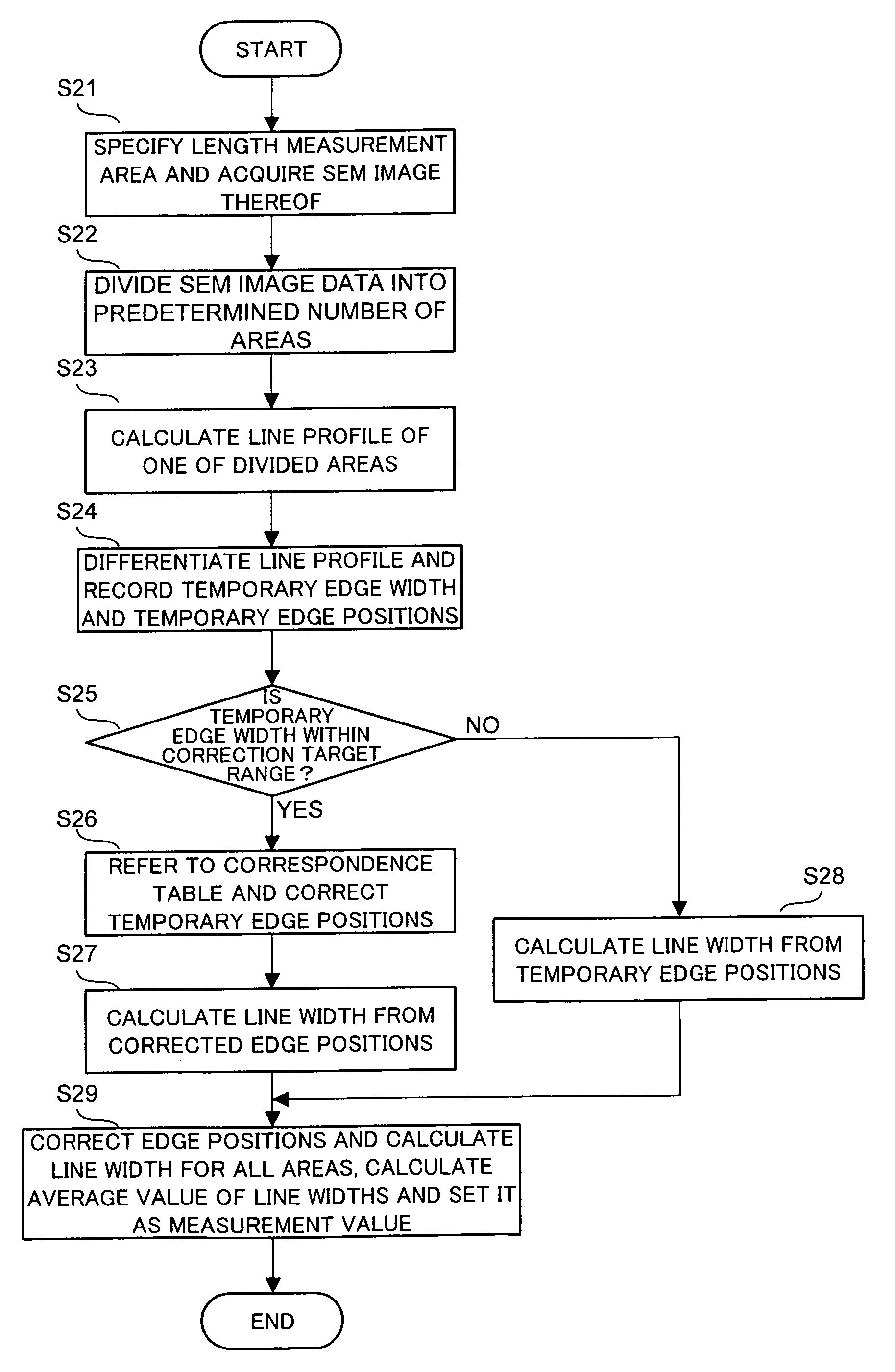
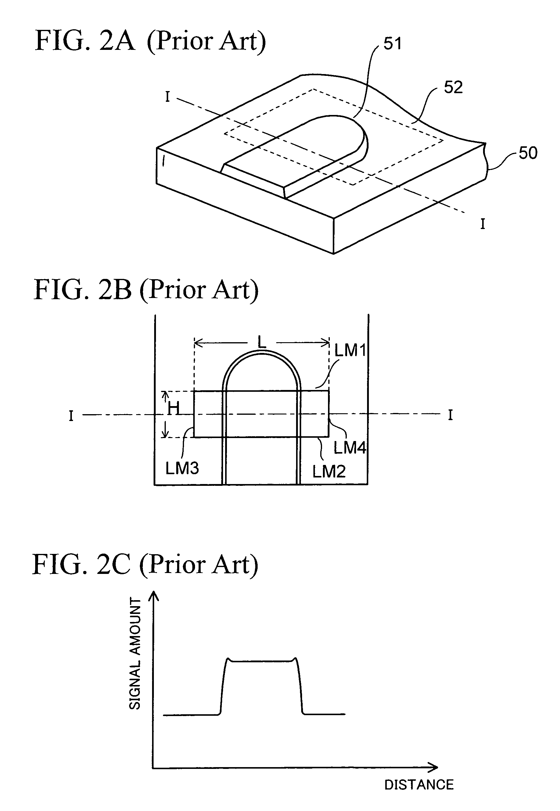
[0034]First, a configuration of a scanning electron microscope (SEM) used as a pattern measurement apparatus is described. Next, a general method of measuring the line width of a pattern is described. Then, the relationship between the width of an edge portion and the beam width (beam diameter) is described, and a technique that allows accurate length measurement of a line width even when an edge width is small is described. Lastly, a pattern measurement method to which the pattern detection method of the present invention is applied is described.

[0035](Configuration of Scanning Electron Microscope)

[0036]FIG. 1 is a configuration view of a scanning electron microscope according to this embodiment.

[0037]This scanning electron microscope 100 mainly includes an electron scanning unit 10, a signal processor 30, an image display unit 40, a storage unit 55, and a controller 20 controlling e...


PUM


Abstract

A pattern measurement apparatus includes a beam intensity distribution creation unit to scan a charged particle beam over a reference pattern having edge portions formed at a right angle to create a line profile of the reference pattern and thus create a reference-beam intensity distribution, an edge width detection unit to determine line profiles for pattern models including edges formed at various inclination angles by use of the reference-beam intensity distribution and calculate edge widths reflecting an influence of a width of a reference beam, and a correspondence table creation unit to calculate correction values for edge positions from the calculated edge widths and the pattern models and create a correspondence table in which the edge widths and the correction values are associated with one another.

Description

CROSS-REFERENCE TO RELATED APPLICATIONS[0001]This application is a continuation of prior International Patent Application No. PCT / JP2008 / 073708, filed Dec. 26, 2008, the entire contents of which are incorporated herein by reference.BACKGROUND OF THE INVENTION[0002]1. Field of the Invention[0003]The present invention relates to a pattern measurement apparatus and a pattern measurement method using a charged particle beam, and in particular to a pattern measurement apparatus and a pattern measurement method capable of accurate length measurement regardless of the edge width of a pattern.[0004]2. Description of the Related Art[0005]As a method of measuring the line widths of patterns, there is a method such as a one performing measurement using a scanning electron microscope (SEM). In the scanning electron microscope, a sample is irradiated with and scanned by incident electrons within an electron beam scanning range, and secondary-electrons emitted from the sample are acquired through...

Claims


Application Information

Patent Timeline
Patent Type & Authority Patents(United States)
IPC IPC(8): H01J37/28H01J37/22G01B15/00
CPCG01B15/00H01J37/265H01J37/28H01J2237/22H01J2237/24578H01L2924/0002H01J2237/2817H01L22/12H01L2924/00
Inventor MATSUMOTO, JUN
Owner ADVANTEST CORP
Why Eureka
Try Eureka