Motor drive circuit

a technology of motor drive and circuit, which is applied in the direction of motor/generator/converter stopper, dynamo-electric converter control, dc motor rotation control, etc., can solve the problem of higher cost of the motor drive circui

Active Publication Date: 2012-12-11
SEMICON COMPONENTS IND LLC
View PDF6 Cites 3 Cited by
  • Summary
  • Abstract
  • Description
  • Claims
  • Application Information

AI Technical Summary

Benefits of technology

[0012]This invention is directed to solve the problem addressed above, and intends to prevent the braking force from being caused when the power supply voltage is reduced to less than the predetermined voltage by avoiding the formation of the loop while suppressing the rise in the voltage at the occurrence of the kickback at a low cost.

Problems solved by technology

However, the method requires increasing a size of the Zener diode as a size of the motor increases, resulting in a higher cost of the motor drive circuit.

Method used


Image

  • Motor drive circuit
  • Motor drive circuit
  • Motor drive circuit

Examples


Embodiment Construction

[0017]A motor drive circuit according to an embodiment of this invention is hereafter described in detail.

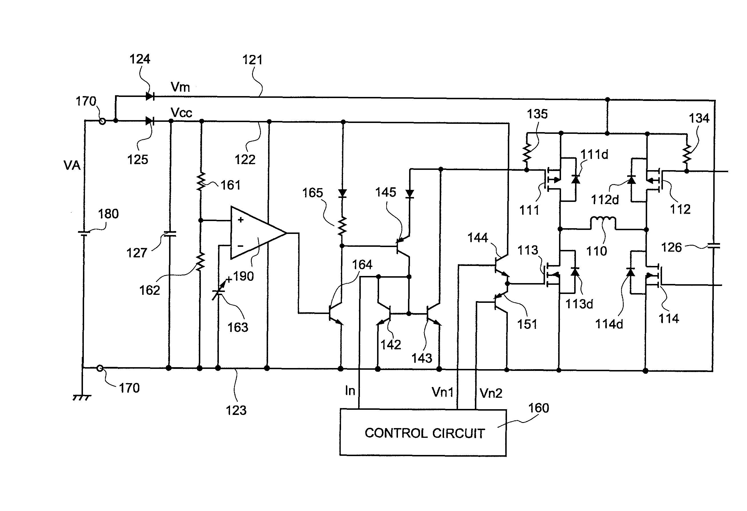
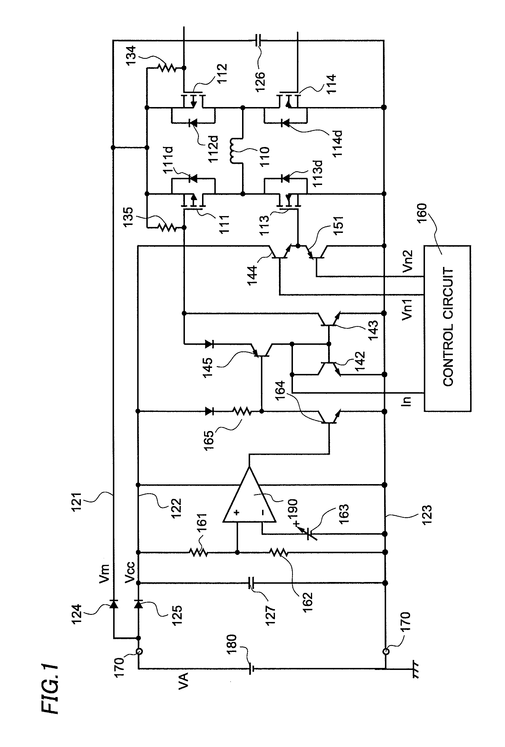
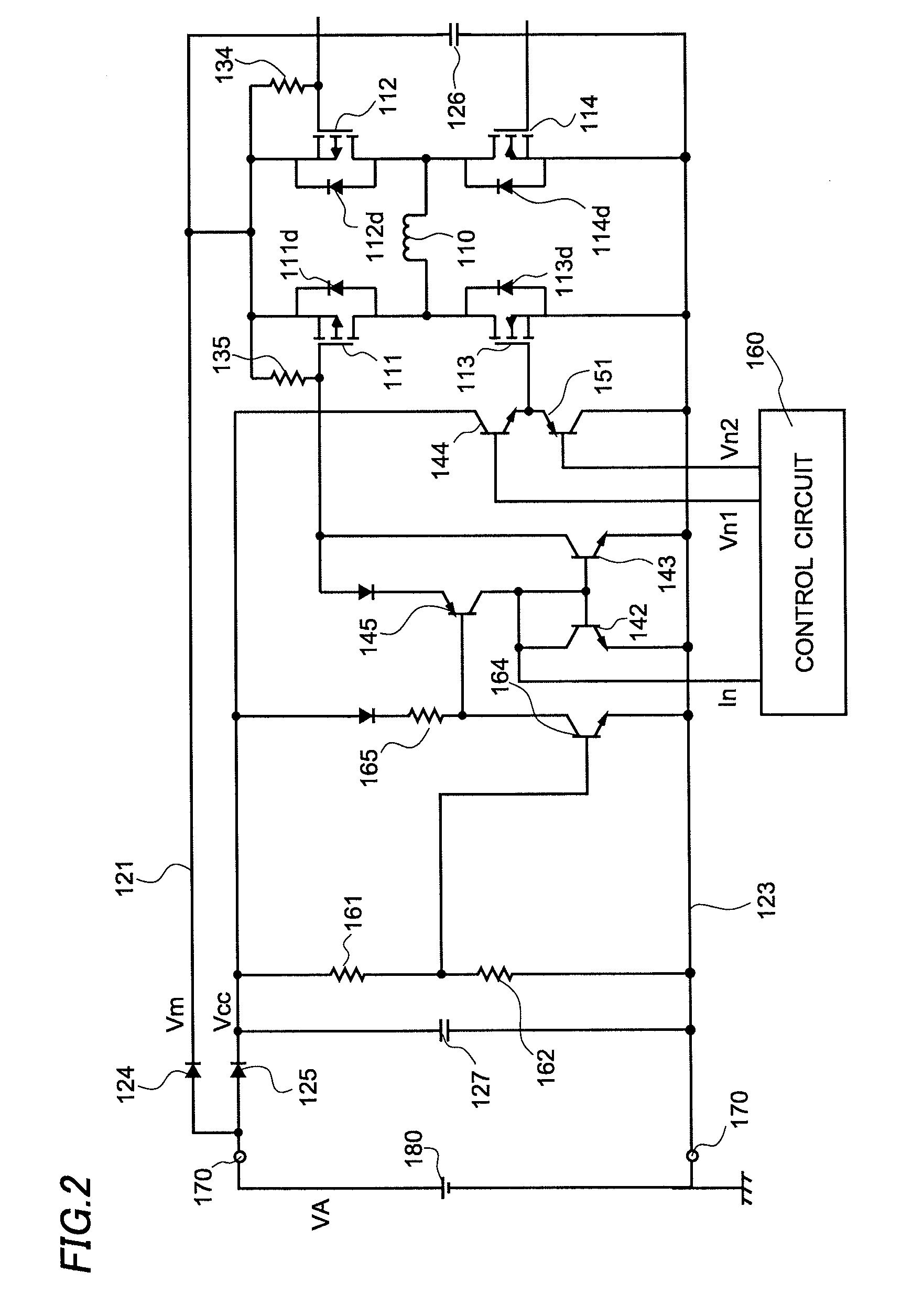
[0018]FIG. 1 shows an example of a structure of the motor drive circuit according to the embodiment of this invention. The motor drive circuit drives a single-phase motor such as a fan motor, for example, and controls an electric current flowing through a motor coil 110. The motor drive circuit is formed to include P-channel type MOSFETs 111 and 112, N-channel type MOSFETs 113 and 114, power supply lines 121 and 122, a ground line 123, diodes 124 and 125, capacitors 126 and 127, NPN type transistors 142-144, and 164, PNP type transistors 145 and 151, a control circuit 160, a comparator 190, resistors 161, 162 and 135, a reference voltage source 163, and a connector 170.

[0019]First, the structure of the motor drive circuit according to the embodiment is described in detail.

[0020]The MOSFETs 111-114 constitute an H-bridge circuit. To describe the H-bridge circuit more in detail, s...


PUM


Abstract

This invention provides a motor drive circuit, which makes it possible to prevent braking when a power supply voltage is lower than a predetermined voltage while suppressing at a low cost a rise in a voltage on a power supply line when a kickback occurs. The motor drive circuit is formed to include first and second power supply lines connected with and shunted from a power supply, an H-bridge circuit, and a means to control the H-bridge circuit. The means controls the H-bridge circuit so that a regeneration path is not created in the H-bridge circuit when the power supply voltage is lower than a predetermined voltage.

Description

CROSS-REFERENCE OF THE INVENTION[0001]This application claims priority from Japanese Patent Application No. 2009-046353, the content of which is incorporated herein by reference in its entirety.BACKGROUND OF THE INVENTION[0002]1. Field of the Invention[0003]This invention relates to a motor drive circuit.[0004]2. Description of the Related Art[0005]When driving a motor with an H-bridge circuit, it is necessary to prevent MOSFETs from being destroyed by a rise in a voltage caused at an occurrence of a kickback.[0006]Japanese Patent Application Publication No. 2005-269885 discloses a method to suppress the rise in the voltage at the occurrence of the kickback using a Zener diode, for example. However, the method requires increasing a size of the Zener diode as a size of the motor increases, resulting in a higher cost of the motor drive circuit.[0007]On the other hand, Japanese Patent Application Publication No. 2007-259657 discloses a motor drive circuit that prevents the destruction ...

Claims


Application Information

Patent Timeline
Patent Type & Authority Patents(United States)
IPC IPC(8): H02P6/08H02P7/28
CPCH02P7/0044H02P29/025H02P7/04
Inventor NOIE, JOJI
Owner SEMICON COMPONENTS IND LLC
Why Eureka
Try Eureka