Device and method for determining the deviation of the carrier frequency of a mobile radio device from the carrier frequency of a base station

a mobile radio device and carrier frequency technology, applied in the direction of transmission monitoring, pulse technique, synchronisation arrangement, etc., can solve the problems of high work load on both the digital signal processor and the data bus via which the data is transmitted, and the doppler frequency shift, so as to reduce the amount of data transferred, reduce the workload, and reduce the effect of computation operations

Inactive Publication Date: 2012-12-11
INTEL CORP
View PDF12 Cites 0 Cited by
  • Summary
  • Abstract
  • Description
  • Claims
  • Application Information

AI Technical Summary

Benefits of technology

[0027]One advantage of the invention is the combination of the terms to form groups. The third unit, which carries out the final computation operations for determination of the frequency discrepancy, does not need to be supplied with all the terms as individual results, by virtue of the formation of groups, but only with the respective intermediate results for the groups. This reduces the amount of data transferred on the data bus which is arranged between the second and the third unit, and the third unit has to carry out fewer computation operations. A further advantage of the formation of groups is that the groups can be formed on the basis of criteria which are worthwhile for the further calculations, and involve little effort. For example, it is advantageous to combine in a group the terms which relate to selection of the strongest-signal transmission paths from each base station. This can contribute to a reduction in the Doppler effect. The combination of a number of paths for result formation also increases the result quality when using diversity.
[0028]The first unit and the second unit are advantageously in the form of hard-wired circuits. This measure is advantageous since the work steps to be carried out by the first and second units are admittedly computation-intensive, but are uncomplicated and can thus be carried out easily by hardware.
[0029]A further advantageous refinement of the invention provides for the third unit to be formed by a digital signal processor. This ensures that the device according to the invention has a high degree of flexibility. Furthermore, the computation operations relating to the calculation of the frequency discrepancy to be carried out by the digital signal processor are few in number, so that the digital signal processor has sufficient remaining computation capacity for other tasks. For example, the digital signal processor can also predetermine the criteria on the basis of which the terms are sorted into groups in the second unit. The digital signal processor can also carry out further control tasks.
[0030]According to one preferred refinement of the invention, the first unit is designed to calculate complex products, with a complex product being formed from at least two different pilot symbols in the sequence received by the mobile radio, and the argument of the complex product indicating the phase difference between the two pilot symbols. As an alternative to this type of calculation, the phase angles of the at least two different pilot symbols could also first of all be calculated separately from one another, with it being possible for the phase difference to then be calculated from the phase angles.
[0031]The first unit preferably contains a multiplier, which has a first input and a second input. The first input is preceded by a circuit branch which contains a delay element and a unit for transformation of a complex value to its complex-conjugate value. The circuit branch is fed with the one pilot symbol, and the second input is fed with the other pilot symbol.
[0032]The delay time in the delay element can advantageously be varied and predetermined.

Problems solved by technology

A further cause of frequency shifts may be temperature fluctuations.
Furthermore, movements of the mobile radio with respect to the base station lead to Doppler frequency shifts.
This leads to a high work load on both the digital signal processor and the data bus via which the data is transmitted.

Method used


Image

  • Device and method for determining the deviation of the carrier frequency of a mobile radio device from the carrier frequency of a base station
  • Device and method for determining the deviation of the carrier frequency of a mobile radio device from the carrier frequency of a base station
  • Device and method for determining the deviation of the carrier frequency of a mobile radio device from the carrier frequency of a base station

Examples


Embodiment Construction

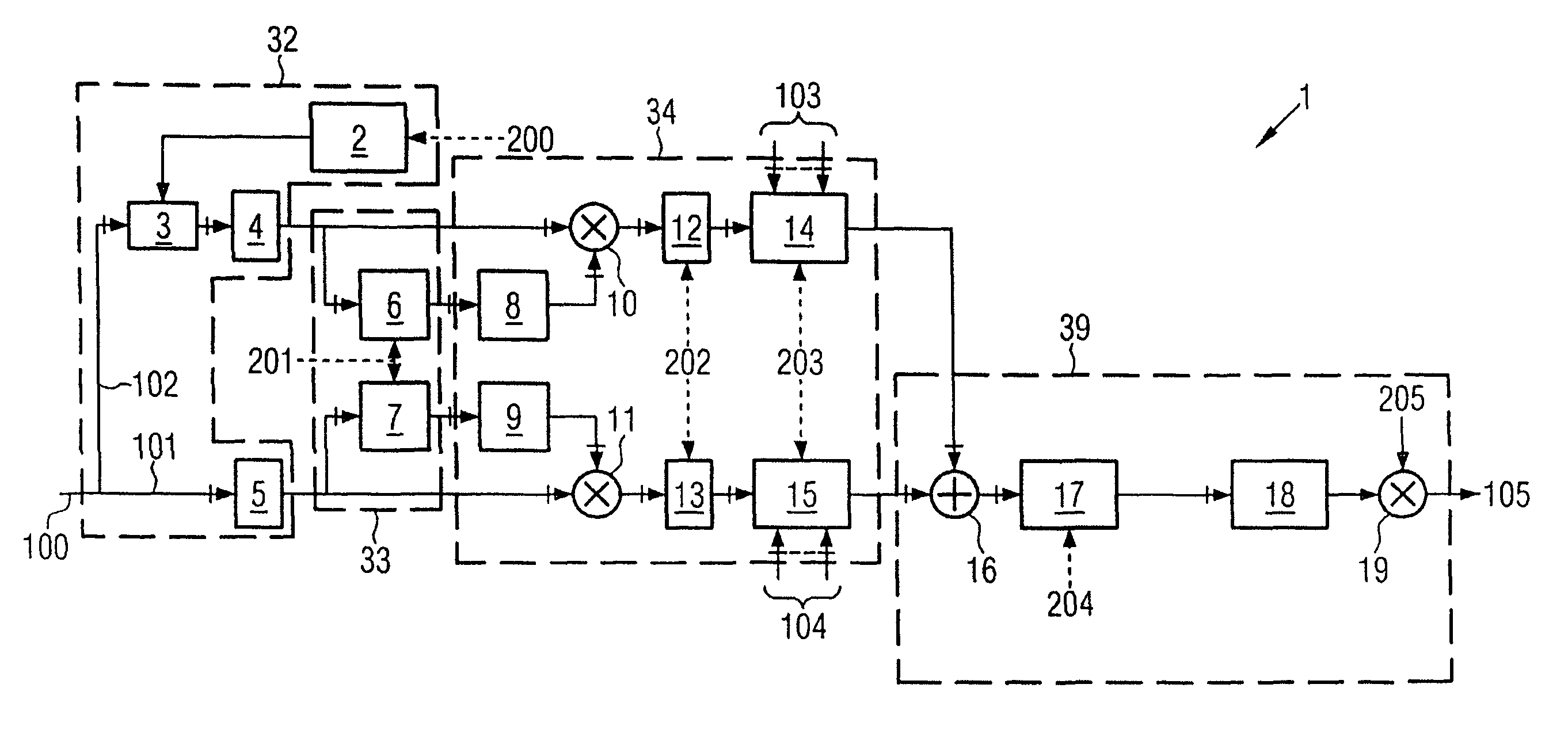
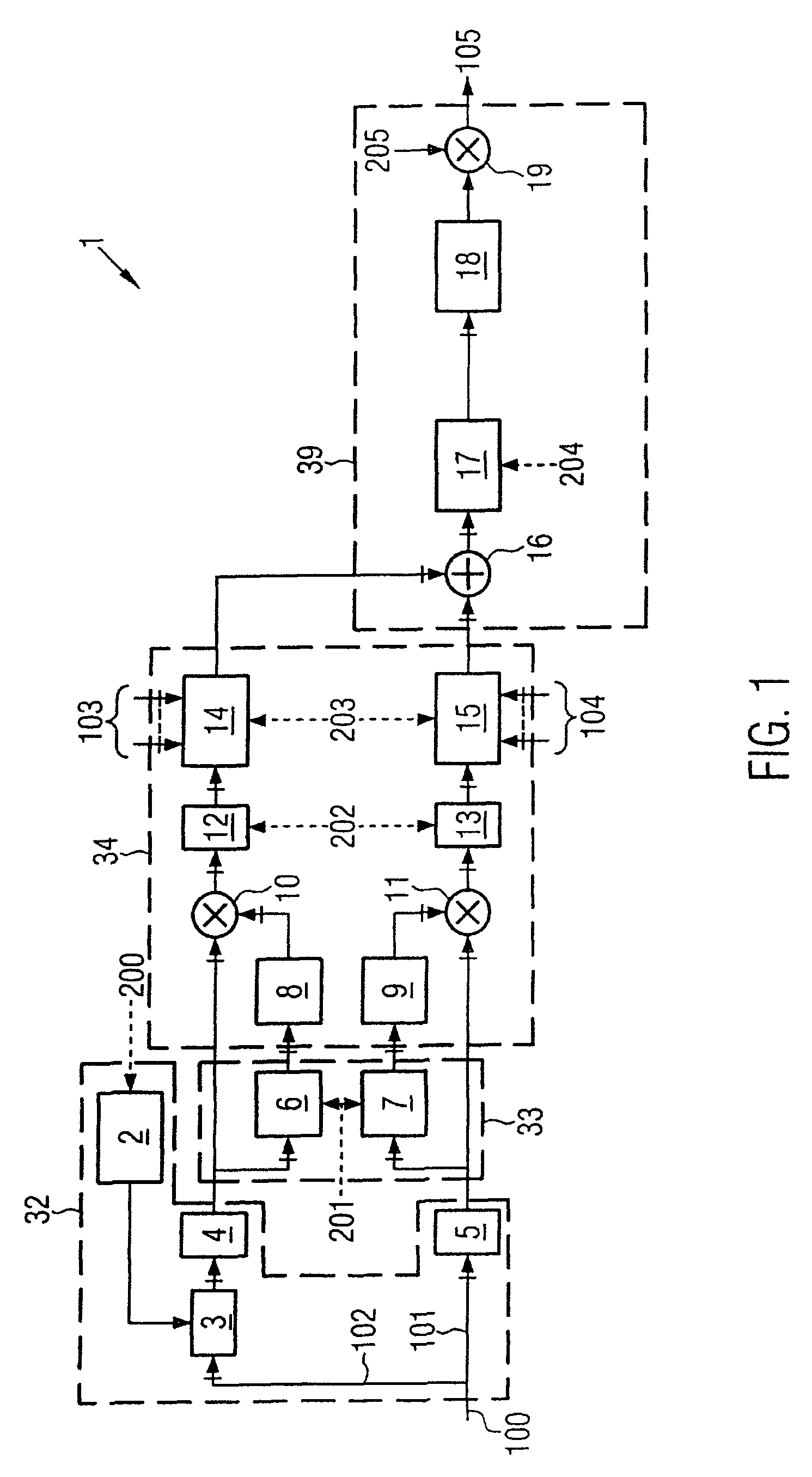
[0051]FIG. 1 shows the schematic circuit diagram of a circuit 1, which may be a component of one exemplary embodiment of the device according to the invention, as shown in FIG. 3. Since the method of operation of the exemplary embodiment shown in FIG. 3 results from the method of operation of the circuit 1, the circuit 1 must be explained first of all.

[0052]The circuit 1 is integrated in a mobile radio. Pilot signals received by the mobile radio are demodulated in a RAKE receiver, and are converted to pilot symbols 100. The pilot symbols 100 are passed to the circuit 1 at a data rate of, for example, 15 ks / s. This example is based on the assumption that the base station from which the pilot symbols 100 were originally transmitted is being operated using the STTD operating mode. In the STTD operating mode, the base station transmits its signals with the aid of two antennas 1 and 2. The pilot symbols 100 are split in the circuit 1 into two data paths, with the pilot symbols 101 associ...


PUM


Abstract

A device for determination of the frequency discrepancy (105) between a mobile radio and a base station which is transmitting a sequence of symbols, having a unit (6-11) for calculation of terms, with one term being formed from two symbols in the sequence received by the mobile radio, and in which case the phase difference of the two symbols can be determined from the term, a unit (14, 15) for formation of groups from the terms, with one term being assigned to one group on the basis of features of the symbols on which it is based, and a unit (39) for calculation of the discrepancy (105) on the basis of a group.

Description

CROSS-REFERENCE TO RELATED APPLICATION[0001]This application is a continuation of copending International Application No. PCT / DE03 / 02026 filed Jun. 17, 2003 which designates the United States, and claims priority to German application no. 102 30 150.6 filed Jul. 4, 2002.TECHNICAL FIELD OF THE INVENTION[0002]The present invention relates to a device by means of which it is possible to determine the discrepancy between the carrier frequency of a mobile radio and the carrier frequency of a base station. The invention also relates to a corresponding method.DESCRIPTION OF RELATED ART AND BACKGROUND OF THE INVENTION[0003]In order to transmit symbols between a base station and a mobile radio, the symbols are modulated onto a carrier frequency in the transmitter, and are demodulated in the receiver. In this case, the mobile radio must use the same carrier frequency as the base station. However, if there is a discrepancy in the carrier frequency in the mobile radio, the discrepancy must be d...

Claims


Application Information

Patent Timeline
Patent Type & Authority Patents(United States)
IPC IPC(8): H03K9/00H04B7/26H04L27/00H04L27/14
CPCH04L27/14H04W56/0035H04L2027/0067H04L2027/0087H04W92/10
Inventor BECKER, BURKHARDNEUHAUS, HOLGER
Owner INTEL CORP
Why Eureka
Try Eureka