Method and system for controlling an aircraft air conditioning system with optimised fuel consumption

a technology of air conditioning system and fuel consumption, which is applied in the direction of domestic cooling apparatus, energy-efficient board measures, lighting and heating apparatus, etc., can solve the problems of increasing the fuel consumption, increasing the process air mass flow, and increasing so as to reduce the fuel consumption of aircraft, reduce excess weight and extra costs of additional equipment, and reduce the effect of excess weigh

Active Publication Date: 2012-12-18
AIRBUS OPERATIONS GMBH
View PDF9 Cites 22 Cited by
  • Summary
  • Abstract
  • Description
  • Claims
  • Application Information

AI Technical Summary

Benefits of technology

[0014]Finally, the process air mass flow and the ambient air mass flow are controlled in dependence on a predetermined cooling capacity of the aircraft air conditioning system such that the fuel consumption of the aircraft is minimized. In other words, in the method according to the invention for controlling an aircraft air conditioning system both the influence of a variation in the process air mass flow and the influence of a variation in the ambient air mass flow on the fuel consumption of the aircraft are taken into account when controlling the aircraft air conditioning system. By taking both operating variables of the aircraft air conditioning system which influence the fuel consumption of the aircraft into account, when compared with control methods known from the prior art, which only provide for a minimization of the process air mass flow, the method according to the invention for controlling an aircraft air conditioning system enables the fuel consumption entailed by the operation of the aircraft air conditioning system to be minimized in all operating states of the aircraft air conditioning system.
[0015]The process air mass flow and the ambient air mass flow can be controlled by means of an electronic control unit. As the logic which is required to control the process air mass flow and the ambient air mass flow is relatively simple, the control function for controlling the process air mass flow and the ambient air mass flow can also be integrated into an existing electronic control unit without any problems. Excess weight and extra costs due to additional equipment can as a result be avoided. The method according to the invention can therefore also be used relatively easily in existing aircraft air conditioning systems.
[0024]In the system according to the invention for controlling an aircraft air conditioning system the electronic control unit is preferably also adapted, upon controlling the process air mass flow and the ambient air mass flow, to select the pair of values of the process air mass flow and the ambient air mass flow from the plurality of pairs of values of the process air mass flow and the ambient air mass flow associated with a predetermined cooling capacity of the aircraft air conditioning system which enables the fuel consumption of the aircraft to be minimized.

Problems solved by technology

The greater the quantity of hot process air which must be provided as engine bleed air by the engines of an aircraft, the higher the fuel consumption of the aircraft.
An increase in the fuel consumption when there is an increase in the process air mass flow also occurs when using compressors which are formed separately from the engines, as the electrical energy which is required to drive the compressors must be provided by the engines.
However the maximum cooling capacity which is to be produced by the compression and expansion unit is as a rule limited by the system pressure, i.e. the pressure at which the process air is supplied to the compression and expansion unit by the engines or the compressors formed separately from the engines.
However, on account of the fact that the flaps project out of the aircraft outer skin in the open state, the opening of the flaps controlling the flow cross sections of the ram air inlet duct and / or the ram air outlet duct increases the aerodynamic drag and therefore the fuel consumption of the aircraft.
However the increase in the ambient air mass flow through the heat exchanger unit of the air conditioning unit which is required to compensate for the reduced process air mass flow when the cooling capacity requirement of the aircraft cabin is constant results in an increase in the fuel consumption of the aircraft.

Method used


Image

  • Method and system for controlling an aircraft air conditioning system with optimised fuel consumption
  • Method and system for controlling an aircraft air conditioning system with optimised fuel consumption
  • Method and system for controlling an aircraft air conditioning system with optimised fuel consumption

Examples


Embodiment Construction

[0033]The aircraft air conditioning system 10 which is shown in FIG. 5 comprises an air conditioning unit 12 with a compression and expansion unit 14 as well as a heat exchanger unit 16. The air conditioning unit 12 of the aircraft air conditioning system 10 also comprises a number of different regulating and control valves 18.

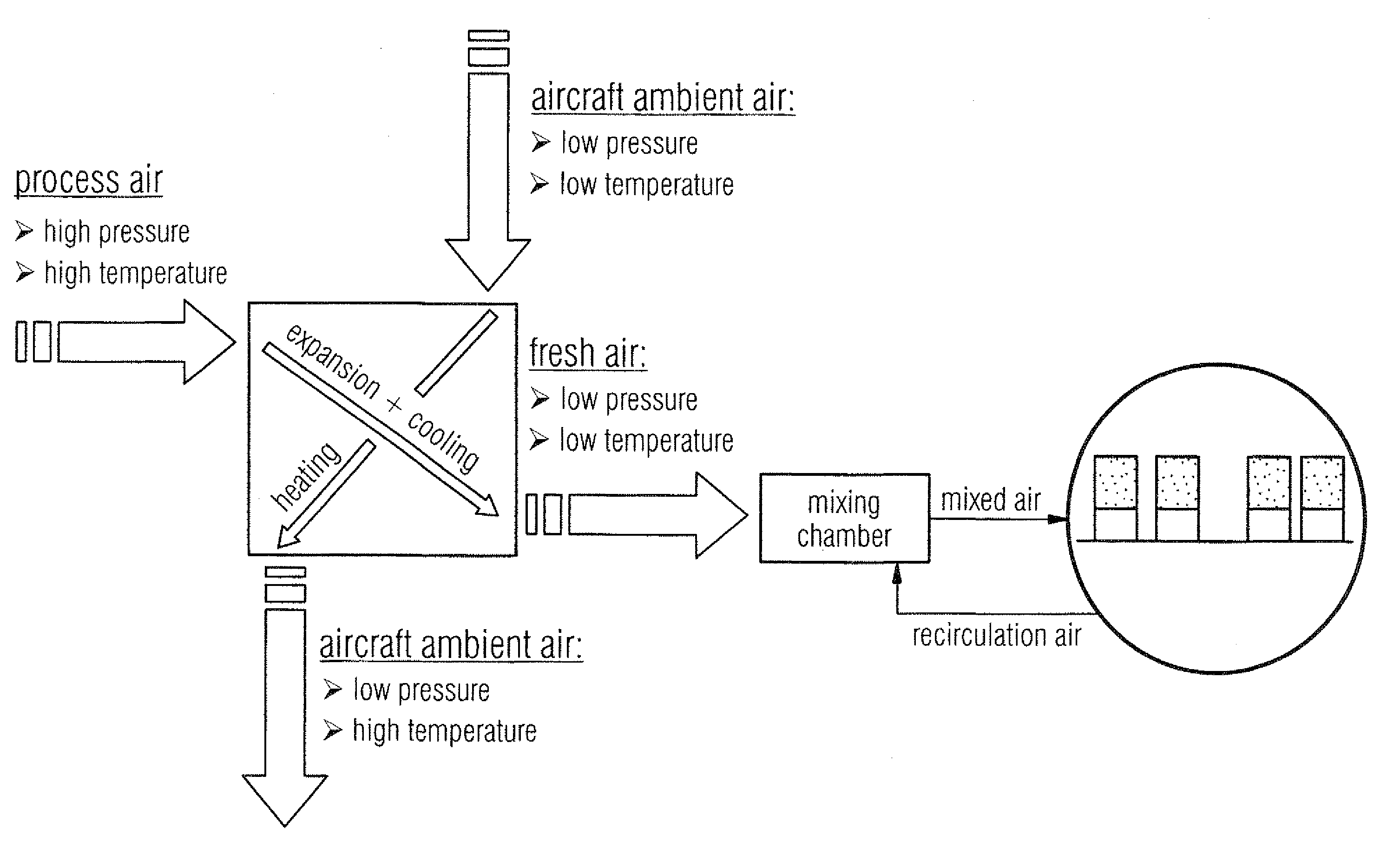
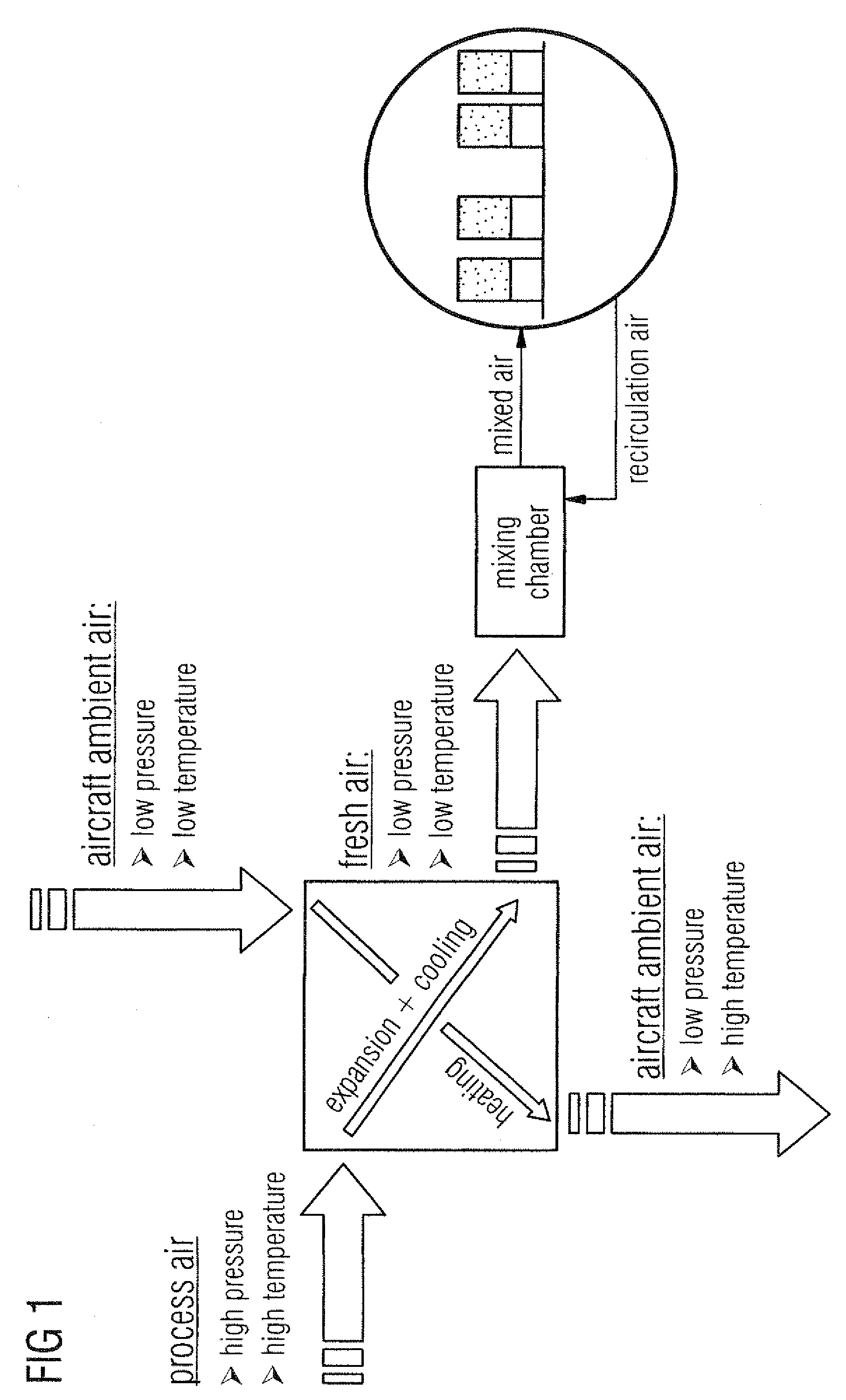
[0034]Process air which is bled off the engines of the aircraft or produced by compressors formed separately from the engines is supplied to the air conditioning unit 12 of the aircraft air conditioning system 10 at a high temperature and under high pressure. The process air supply into the air conditioning unit 12 is controlled by means of a process air supply regulating system 20. The process air is treated in the air conditioning unit 12 upon flowing through the heat exchanger unit 16 as well as the compression and expansion unit 14 such that it leaves the air conditioning unit 12 as fresh air which is expanded and cooled down to a desired temperature. The ...


PUM


Abstract

In a method for controlling an aircraft air conditioning system, a correlation is established between a plurality of values of a process air mass flow supplied to an air conditioning unit of the aircraft air conditioning system and the fuel consumption of the aircraft. A correlation is also established between a plurality of values of an ambient air mass flow which is used to cool the process air mass flow supplied to the air conditioning unit of the aircraft air conditioning system and the fuel consumption of the aircraft. The process air mass flow and the ambient air mass flow are controlled in dependence on a predetermined cooling capacity of the aircraft air conditioning system such that the fuel consumption of the aircraft is minimized.

Description

[0001]This application claims priority to U.S. Provisional Patent Application No. 61 / 108,665, filed on Oct. 27, 2008; and / or German Patent Application No. 102008053320 filed on Oct. 27, 2008.TECHNICAL FIELD[0002]The invention relates to a method and a system for controlling an aircraft air conditioning system with optimized fuel consumption.BACKGROUND[0003]So-called air-based air conditioning systems are usually used at present in commercial aircraft to air-condition the aircraft cabin. An aircraft air conditioning system serves to cool the aircraft cabin, which would otherwise be overheated due to thermal loads, such as, e.g. insulation, body heat of the passengers and waste heat from equipment present on board the aircraft. The aircraft air conditioning system in addition adequately supplies fresh air into the aircraft cabin to ensure that a prescribed minimum proportion of oxygen is present in is the aircraft cabin. The structure and the operating principle of an air-based air co...

Claims


Application Information

Patent Timeline
Patent Type & Authority Patents(United States)
IPC IPC(8): F25B9/00
CPCB64D13/06B64D2013/0618B64D2013/0688Y02T50/56Y02T50/50
Inventor KELNHOFER, JUERGEN
Owner AIRBUS OPERATIONS GMBH
Why Eureka
Try Eureka