
Detection system for localizing defective seals in heat exchangers

a heat exchanger and seal technology, applied in the direction of fluid tightness measurement, lighting and heating apparatus, instruments, etc., can solve the problems of defective joints, failure to survive in intact for the expected life time under normal working conditions, and defective joints, etc., to reduce or eliminate customer returns, increase mass, and widen the effect of width or breadth

Active Publication Date: 2012-12-18
VALEO INC +1
View PDF10 Cites 0 Cited by
  • Summary
  • Abstract
  • Description
  • Claims
  • Application Information

AI Technical Summary

Benefits of technology

[0015]An aspect of the present invention provides for an assembly, and, for example, a heat exchanger that will be leak proof at male to female fittings or connections, and that will be durable and not abnormally leak in the field. Further aspects of the present invention provide for a method of detecting a defective joint or incorrectly functioning fluid connection, due to false seals at the male to female portion of the fitting or connection, prior to them being shipped outside of the factory or production area. Further aspects of the present invention reduce the defect level in the field by detecting both false seals and potential premature leaks in the manufacturing plant when initially tested as part of the normal leak test process.
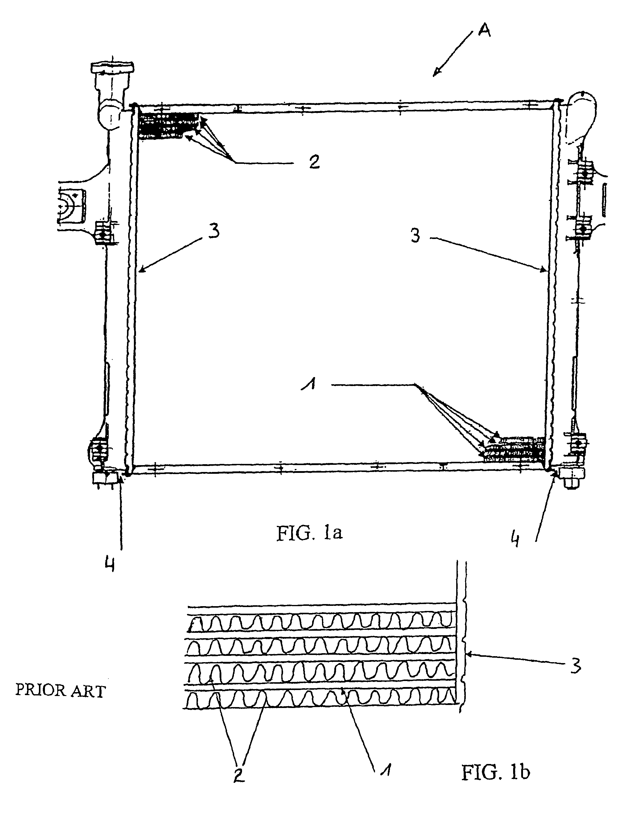
[0025]The present invention, in all its embodiments, results, thereby, in markedly better detection of ‘non-conforming’ or future ‘leaking’ heat exchanger assemblies, especially heat exchanger assemblies having a core comprising a header and tanks attached to the core at the header in a way to form a tank to header leak proof seal, that reduces or eliminates the occurrence of ‘non-conforming’ or future ‘leaking’ assemblies reaching the customer in less than optimal condition for performance, by detecting leaks at the initial assembly manufacture stage.
[0027]Aspects of the present invention provide distinct advantages for tank to header joints employing seals. For heat exchangers, defective or ‘temporarily sealed’ assemblies, that might normally pass ordinary leak tests used in the industry, can be detected and contained within the manufacturing plant, reducing or eliminating customer returns.
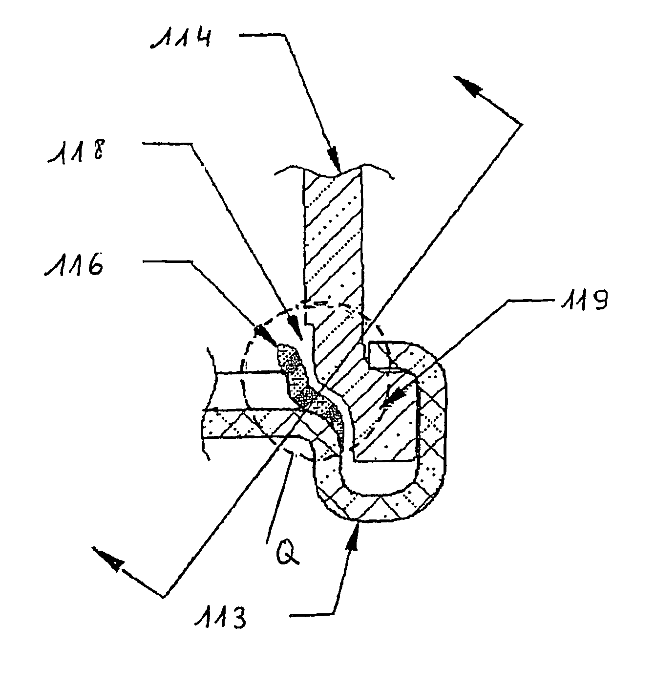
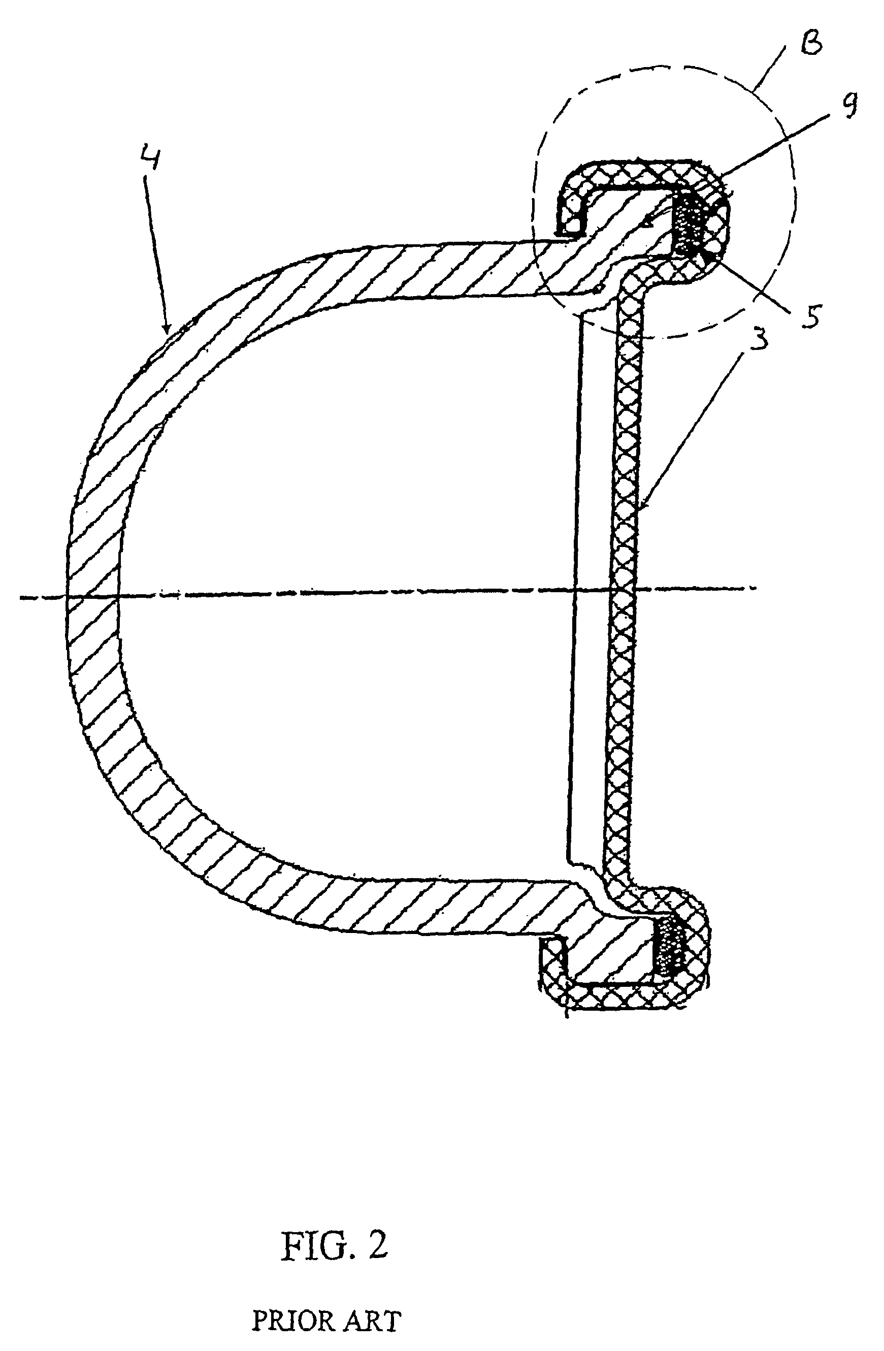
[0028]In preferred embodiments of the present invention, the section of the end tank or side in contact with the header is of greater width or breadth than the side at other areas of the header. This section of the end tank is often called a ‘foot’ or ‘tank foot’, and this term is common in the field of heat exchangers. Since the tank foot serves as a base or supporting section at the tank to header joint area, the tank foot, due to its shape and increased mass, allows the header to be bent on or ‘crimped’ on or to the end tank, in order to provide an intimate connection and, maintain a leak tight or leak proof seal necessary to prevent fluid escape from the interior of the tank.
[0030]The aspects of the present invention that provide for a connection with a leak path from the area of normal presence of the sealing means (O-ring or gasket) to an area outside or external to the connection, where detection, preferably, by traditional leak testing involving pressure testing, or visual examination, or other means consistent with detection of leaks, can be done prior to releasing the connection, assembly or end product, prior to sale or removal from its site of production. The type of connection can be any type of male and female type connection, i.e. connection with female and male portions. This connection can preferably be part of a heat exchanger assembly. Connections can be held together in many ways such as, preferably, threading or snap fitting. More preferably, the type of connection is a threaded connection. These aspect of the present invention, by providing for a means such as a leak path to the area where a sealing means is normally present in such connections, allows for detection of problems with the presence (or lack thereof) of the ‘correct’ leak tight or leak proof connections and defectives joints, so that potential future leaks are detected prior to leaving the production floor. These aspects of the present invention, therefore, can be used in any design whereby the male and female portions provide for an unintended or false seal at an area that may leak prior to the end of the intended or specified product life cycle.

Problems solved by technology

In additional aspects of the present invention, a channel or groove is provided that can detect joints where no seal is provided by a sealing means, however, a false seal leading to a ‘defective joint’ occurs when fabricated.
Particularly in cases where metal to metal contacts take place, that the male and female portions or ‘components’ that form the fitting can form a ‘false seal’ or a seal that is not ‘complete’ or assured to be leak tight or leak proof due to its lack of an appropriate gasket or O-ring, and leading to a defective joint.
By defective joint it is meant that the joint forms a seal that is truly temporary, (“a false seal”), and will not survive in intact for its expected life time under usual working conditions.
The fluid that flows through the connection, though initially not leaking or being found inappropriately outside of the connection area, may find its way (be detected or leak occur at a later time in its normal life cycle) outside of the connection, due to the fact that no O-ring or gasket or similar sealing means is found between the male and female portions of the connection or ‘joint.’ Though such a defective joint may pass through conventional screens such as standard leak testing, the joint may not prove durable (may not last its normal lifetime or be ‘complete’) due to its incorrect assembly and / or formation.
Once the heat exchanger or other part is put into service, the defective joint will eventually ‘loosen’ or otherwise separate one portion from another portion, and, in particular, the female from the male portions, and develop a fluid leak, as opposed to containing the fluid within the interior of the portions at that point.

Method used


Image

  • Detection system for localizing defective seals in heat exchangers
  • Detection system for localizing defective seals in heat exchangers
  • Detection system for localizing defective seals in heat exchangers

Examples


Embodiment Construction

[0054]As described above and herein below, the means for detecting an inappropriate, incomplete or temporary seal, in accordance with an aspect of the present invention, may consist of modifications, deformations, perforations, cut-outs, scratches or the like, that serve as ‘channels’ or ‘grooves’ in the header or end tanks, preferably in the end tank, or in the end tank and header. Therefore, the actual shape or orientation of the means can vary accordingly to how and where it is positioned or the header or end tank. The means for detecting temporary seals (detecting future potential leaks) provides for a positive leak path in the case that the sealing means or gasket is misaligned or improperly positioned in the tank to header joint.

[0055]In a preferred embodiment of the present invention, a positive leak path is formed by a channel or groove located on an end tank. Preferred is where a plurality of channels or grooves is located on the end tanks. Also preferred is where a positiv...


PUM


Abstract

The present invention relates to the field of automotive heat exchanger assemblies, and, in particular, assemblies with cores with headers and end tanks and / or male and female connections. The present invention also relates to a method of making a positive leak path to determine leaks prior to employment of heat exchanger assembles. The present invention further relates to a method of determining whether or not a leak seal is temporary by providing a positive leak path at the point of assembly or initial evaluation or testing a heat exchanger.

Description

CROSS REFERENCE TO RELATED APPLICATIONS[0001]This application is a 35 U.S.C. §371 national stage filing of PCT application Ser. No. PCT / US2005 / 023170, filed Jun. 30, 2005, which itself claimed priority to U.S. application Ser. No. 10 / 881,551, filed Jun. 30, 2004 (now U.S. Pat. No. 7,497,245, issued Mar. 3, 2009) and to U.S. Provisional Patent Application Ser. No. 60 / 623,084, filed Oct. 28, 2004. This application is a continuation-in-part of U.S. application Ser. No. 10 / 881,551, filed Jun. 30, 2004 (now U.S. Pat. No. 7,497,245).FIELD OF INVENTION[0002]The present invention relates to the field of automotive heat exchanger assemblies, and, in particular, heat exchangers with tank and header assemblies or connections and seals between such assemblies. The present invention also relates to a method of making a positive leak path to determine and localize eventual leaks prior to customer assembly plant testing or end customer usage of the heat exchanger.BACKGROUND OF THE INVENTION[0003]A...

Claims


Application Information

Patent Timeline
Patent Type & Authority Patents(United States)
IPC IPC(8): G01M3/04F28F9/02G01M99/00
CPCF28F9/0226G01M3/04
Inventor LORENTZ, JAYGUNN, STEPHENLEROY, ERICLELIEVRE, NICOLAS
Owner VALEO INC
Learn More