
Positive resist composition and method for resist pattern formation

a composition and composition technology, applied in the field of positive resist composition and a method for resist pattern formation, can solve the problems of deterioration in lithography characteristics, inability to conventional resist compositions that cannot achieve both a reduced level of defects and excellent lithography characteristics, so as to achieve excellent lithography characteristics and reduce the level of defects. , the effect of positive resist composition

Active Publication Date: 2009-02-12
TOKYO OHKA KOGYO CO LTD
View PDF5 Cites 5 Cited by
  • Summary
  • Abstract
  • Description
  • Claims
  • Application Information

AI Technical Summary

Benefits of technology

[0009]However, conventional resist compositions have proven incapable of achieving both a reduced level of defects and excellent lithography characteristics. For example, one possible method of reducing the level of defects is a method that involves increasing the hydrophilicity of the base resin, thereby suppressing the occurrence of post-developing deposits and the like. However, increasing the hydrophilicity of the base resin is usually accompanied by a deterioration in the lithography characteristics.
[0023]The present invention is able to provide a positive resist composition and a method for resist pattern formation that are capable of forming resist patterns with excellent lithography characteristics and reduced levels of defects.

Problems solved by technology

However, conventional resist compositions have proven incapable of achieving both a reduced level of defects and excellent lithography characteristics.
However, increasing the hydrophilicity of the base resin is usually accompanied by a deterioration in the lithography characteristics.

Method used


Image

  • Positive resist composition and method for resist pattern formation
  • Positive resist composition and method for resist pattern formation
  • Positive resist composition and method for resist pattern formation

Examples


examples

[0257]As follows is a description of examples of the present invention, although the scope of the present invention is in no way limited by these examples.

examples 1 to 3

Comparative Examples 1 and 2

[0258]Using the formulations and blend quantities shown in Table 1, positive resist composition solutions were prepared by dissolving a component (A), a component (B) and a component (D) in an organic solvent.

TABLE 1Component (A)Component (B)Component (D)Organic solventExample 1Resin 1Resin 2PAG 1PAG 2Amine 1Solvent 1(30)(70)(2.5)(1.5)(0.2)(1150)Example 2Resin 1Resin 2PAG 1PAG 2Amine 1Solvent 1(40)(60)(2.5)(1.5)(0.2)(1150)Example 3Resin 1Resin 2PAG 1PAG 2Amine 1Solvent 1(50)(50)(2.5)(1.5)(0.2)(1150)ComparativeResin 1—PAG 1PAG 2Amine 1Solvent 1example 1(100) (2.5)(1.5)(0.2)(1150)Comparative—Resin 2PAG 1PAG 2Amine 1Solvent 1example 2(100) (2.5)(1.5)(0.2)(1150)

[0259]The abbreviations used in Table 1 have the meanings shown below. Furthermore, the numerical values shown within the parentheses ( ) represent blend quantities (parts by weight).

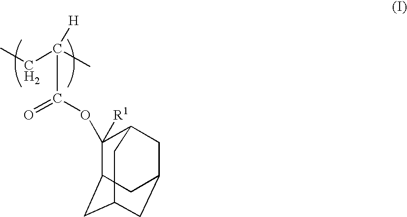
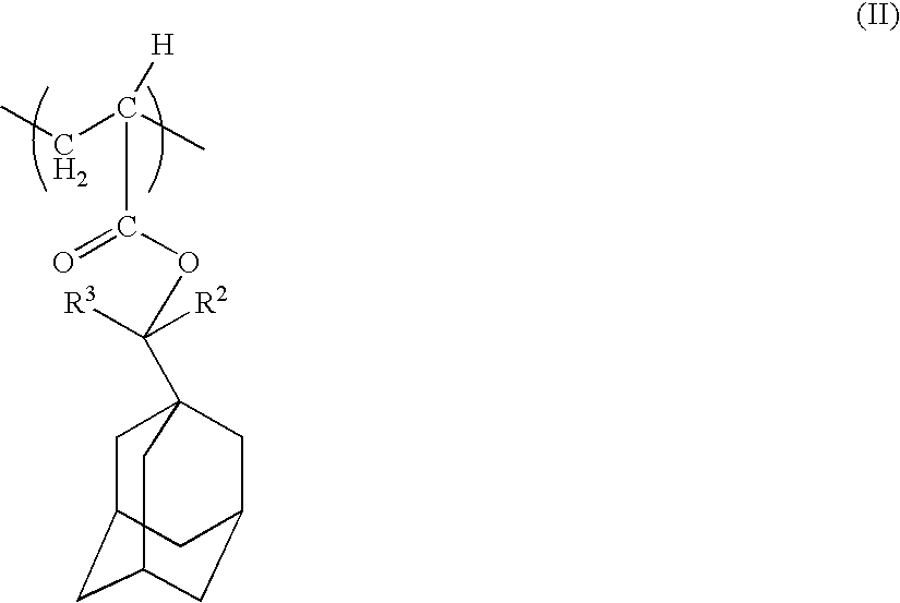
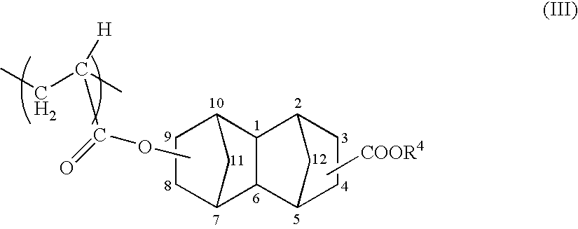
[0260]Resins 1 and 2: The structural formulas of the resins are shown below. In the formulas shown, the numerical values...


PUM

PropertyMeasurementUnit
Contact angleaaaaaaaaaa

Abstract

A positive resist composition includes a resin component (A) that exhibits increased alkali solubility under the action of acid, and an acid generator component (B) that generates acid upon exposure, wherein the resin component (A) is a mixture of a copolymer (A1) that includes a structural unit (a1) derived from an acrylate ester that contains an acid-dissociable, dissolution-inhibiting group, a structural unit (a2) derived from a methacrylate ester that contains a lactone-containing monocyclic group, and a structural unit (a3) derived from an acrylate ester that contains a polar group-containing polycyclic group, and a copolymer (A2) that has a different structure from the copolymer (A1) and has a lower hydrophilicity than the copolymer (A1).

Description

TECHNICAL FIELD[0001]The present invention relates to a positive resist composition and a method for resist pattern formation.[0002]Priority is claimed on Japanese Patent Application No. 2005-024869, filed Feb. 1, 2005, the content of which is incorporated herein by reference.BACKGROUND ART[0003]In recent years, in the production of semiconductor elements and liquid crystal display elements, advances in lithography techniques have lead to rapid progress in the field of miniaturization. Typically, these miniaturization techniques involve shortening the wavelength of the exposure light source. Conventionally, ultra violet radiation typified by g-line and i-line radiation has been used, but nowadays KrF excimer lasers (248 nm) are the main light source used in mass production, and ArF excimer lasers (193 nm) are now also starting to be introduced in mass production. Furthermore, research is also being conducted into lithography techniques that use F2 excimer lasers (157 nm), EUV (extre...

Claims


Application Information

Patent Timeline
IPC IPC(8): G03F7/004G03F7/20
CPCG03F7/0397Y10S430/111G03F7/039
Inventor TAKESHITA, MASARU
Owner TOKYO OHKA KOGYO CO LTD
Learn More