
Buckstay system

a technology of buckstays and steam generators, which is applied in the direction of machines/engines, lighting and heating apparatus, nuclear elements, etc., can solve the problem that the joint does not need to provide expansion, and achieve the effect of preventing dishing

Inactive Publication Date: 2012-12-18
DOOSAN BABCOCK ENERGY AMERICA
View PDF7 Cites 5 Cited by
  • Summary
  • Abstract
  • Description
  • Claims
  • Application Information

AI Technical Summary

Benefits of technology

[0016]A pair of buckstays in accordance with the invention as most broadly stated are associated together at a corner corresponding to a point where a first boiler wall meets a second boiler wall at an angle to form a corner, the associated buckstays being dimensioned and configured for an associated boiler to support such boiler walls in familiar manner. Each buckstay extends across an associated boiler wall. Tie bars are provided in generally conventional manner, and each buckstay engages with a respective tie bar in familiar force transferring manner so that a buckstay forming part of a buckstay assembly can react to horizontal loading in the wall and tend to prevent dishing.
[0017]However, a buckstay in accordance with the invention is particularly characterised in that it is split to comprise at least two rigid elongate buckstay elements which are slideably mounted together in mechanical association in a longitudinal direction. This slideable configuration enables each buckstay, in itself, to accommodate expansion in a longitudinal (that is, in use, horizontal) direction, and in particular to accommodate differential expansion between conditions imposed by the difference between a hot boiler wall and cold buckstays. Since the buckstay itself, by being variable in length via such a mechanical means, accommodates this expansion, the requirement in the prior art to provide potentially complex arrangements of links and brackets between a pair of buckstays at each corner is reduced or eliminated.
[0019]An anchor assembly is associated with each buckstay to enable the buckstay to engage with a tie bar of its associated wall and thus enable the buckstay arrangement in use to transmit bending forces which tend to bend each wall section to each respective buckstay, which therefore resists such bending forces in generally conventional manner.
[0021]To minimise loading balances, it is preferable that each anchor assembly is provided on a buckstay element closely towards a corner formed by its associated wall and the adjacent wall. For example, each buckstay anchor assembly is preferably within 2 m and more preferably within 600 mm of such a corner.
[0026]In the preferred embodiment, a buckstay system comprises horizontal and vertical buckstays which can embody generally familiar principles of design. The buckstay system may be restrained and the weight carried by a support frame, for example in that load carrying restraints are provided between a buckstay and a frame member at a number of horizontal restraint levels. The buckstay system is distinctly characterised in that the horizontal buckstays are split into at least two buckstay elements to accommodate horizontal expansion, most preferably by the vertical buckstays. This dispenses with the need for complex corner bracket arrangements between adjacent horizontal buckstays at a wall corner, and can also confer advantages of flexibility of design, for example in reducing the number of buckstay fixed levels which might be required compared with typical prior art structures.

Problems solved by technology

This joint need not provide for any expansion in a buckstay longitudinal, or horizontal, direction.

Method used


Image

  • Buckstay system
  • Buckstay system
  • Buckstay system

Examples


Embodiment Construction

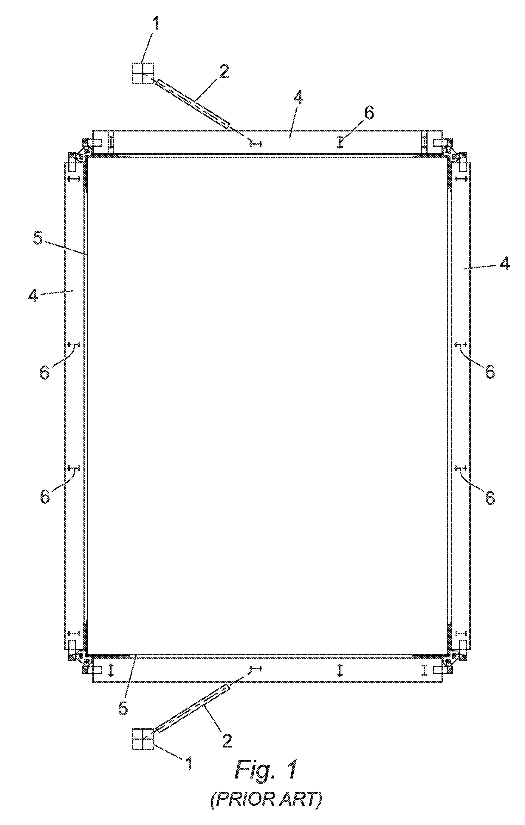
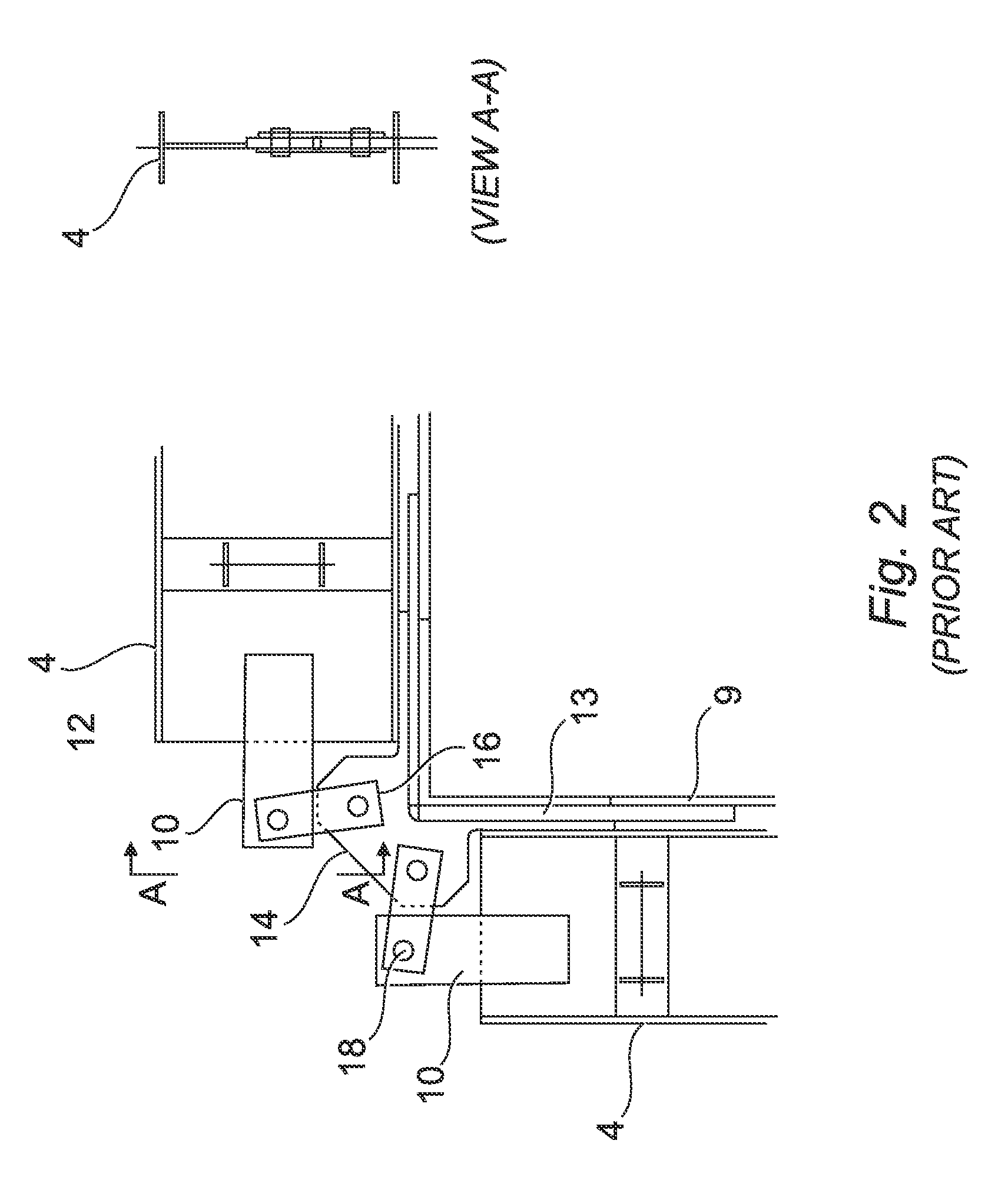
[0036]An arrangement of horizontal buckstays at a restraint level in a typical prior art buckstay system is shown in FIG. 1, with a corner assembly shown in greater detail in FIG. 2.

[0037]Boiler walls 5 of a rectangular boiler are surrounded by an arrangement of horizontal buckstays 4 and vertical buckstays 6. Buckstays are of any suitable known construction, for example comprising steel I beams. The arrangement in FIG. 1 is illustrated at a restraint level, and restraints are provided to transmit load to a support framework 1.

[0038]As can be seen in particular detail in FIG. 2, a complex arrangement of brackets and links is required to accommodate horizontal expansion as the thermal regime changes. Each horizontal buckstay 4 comprises a single monolithic elongate structural member. Each buckstay 4 is provided with an end bracket 10 which is typically welded to the web portion 12 of the I beam comprising the buckstay. Elongate tie bars 9 are provided. A corner tie 13 and corner brac...


PUM


Abstract

A buckstay system is described comprising horizontal buckstays for the walls of a steam generator, for example in plural vertically space assemblies tied with vertical buckstays, in which a buckstay extends generally horizontally across each wall such as to form a connected pair with an adjacent buckstay at each corner; an elongate tie bar formation extends across each wall such as to form a fixedly mounted pair with an adjacent tie bar formation at each corner; an anchor assembly associated with each buckstay and providing engagement means by which each buckstay engages with a respective tie bar; and each horizontal buckstay is split to comprise at least two rigid elongate buckstay elements mounted together to be relatively slideable in a buckstay longitudinal direction.

Description

CROSS-REFERENCE TO RELATED PATENT APPLICATIONS[0001]Not applicable.STATEMENT REGARDING FEDERALLY SPONSORED RESEARCH OR DEVELOPMENT[0002]Not applicable.NAMES OF PARTIES TO A JOINT RESEARCH AGREEMENT[0003]Not applicable.BACKGROUND OF THE INVENTION[0004]1. Field of the Invention[0005]The invention relates to buckstay systems for steam generation apparatus, for example for use with large boilers that are supported by a frame.[0006]2. Description of Related Art[0007]Boilers are commonly constructed of tube banks forming side walls, and typically planar side walls defining a structure of polygonal and usually rectangular section. As the system reaches operating temperature, the walls expand vertically and horizontally. Additionally, furnace pressure variations, pressure differential between fireside and ambient, may produce additional flexing of the tube walls either inwardly or outwardly.[0008]To accommodate gas pressure differential and like effects the boiler walls are typically suppor...

Claims


Application Information

Patent Timeline
IPC IPC(8): G21C13/024
CPCF22B37/208F22B37/24
Inventor ZAMAN, DEWAN SHAMSUZ
Owner DOOSAN BABCOCK ENERGY AMERICA
Learn More