
Recoverable intra-uterine system

a technology of intrauterine system and recovery, which is applied in the field of recovery of intrauterine system, can solve the problems of insufficient stabilization system of contraception, bleeding, microlesions or inflammatory induction, etc., and achieve the effect of preserving the integrity of the endometrium

Active Publication Date: 2012-12-18
ANECOVA SA
View PDF9 Cites 3 Cited by
  • Summary
  • Abstract
  • Description
  • Claims
  • Application Information

AI Technical Summary

Benefits of technology

[0014]An object of the present invention is to propose a recoverable intra-uterine system that removes the drawbacks cited above and in particular guarantees that the system is held in position in the uterine cavity and preserves the integrity of the endometrium, notably during removal of the system.
[0019]Accordingly, thanks to the arrangement of the retaining device at the proximal end of the housing, the system introduced into the uterus is held in position in the region of the cervical channel and the area of contact between the retaining arm or arms of the retaining device and the endometrium is small. The beneficial effects of these features reduce the pressure induced by the intra-uterine system on the uterine cavity.

Problems solved by technology

In particular, existing stabilization systems in the field of contraception, and in particular for retaining a contraceptive IUD in position in the uterus, are not satisfactory.
This is because they can damage the endometrium, not only when retaining the device in position in the uterine cavity, by exerting a constant pressure against the endometrium (causing phenomena of contractions, possibly with hormonal activation), but also during removal of the device, the retaining elements rubbing on the endometrium over a great distance, thereby causing microlesions or inflammatory inductions, or bleeding.
These stabilizing fins are liable to damage the endometrium, notably during removal of the device, and thereby to reduce the chances of successful subsequent implantation of the embryo.

Method used


Image

  • Recoverable intra-uterine system
  • Recoverable intra-uterine system
  • Recoverable intra-uterine system

Examples


Embodiment Construction

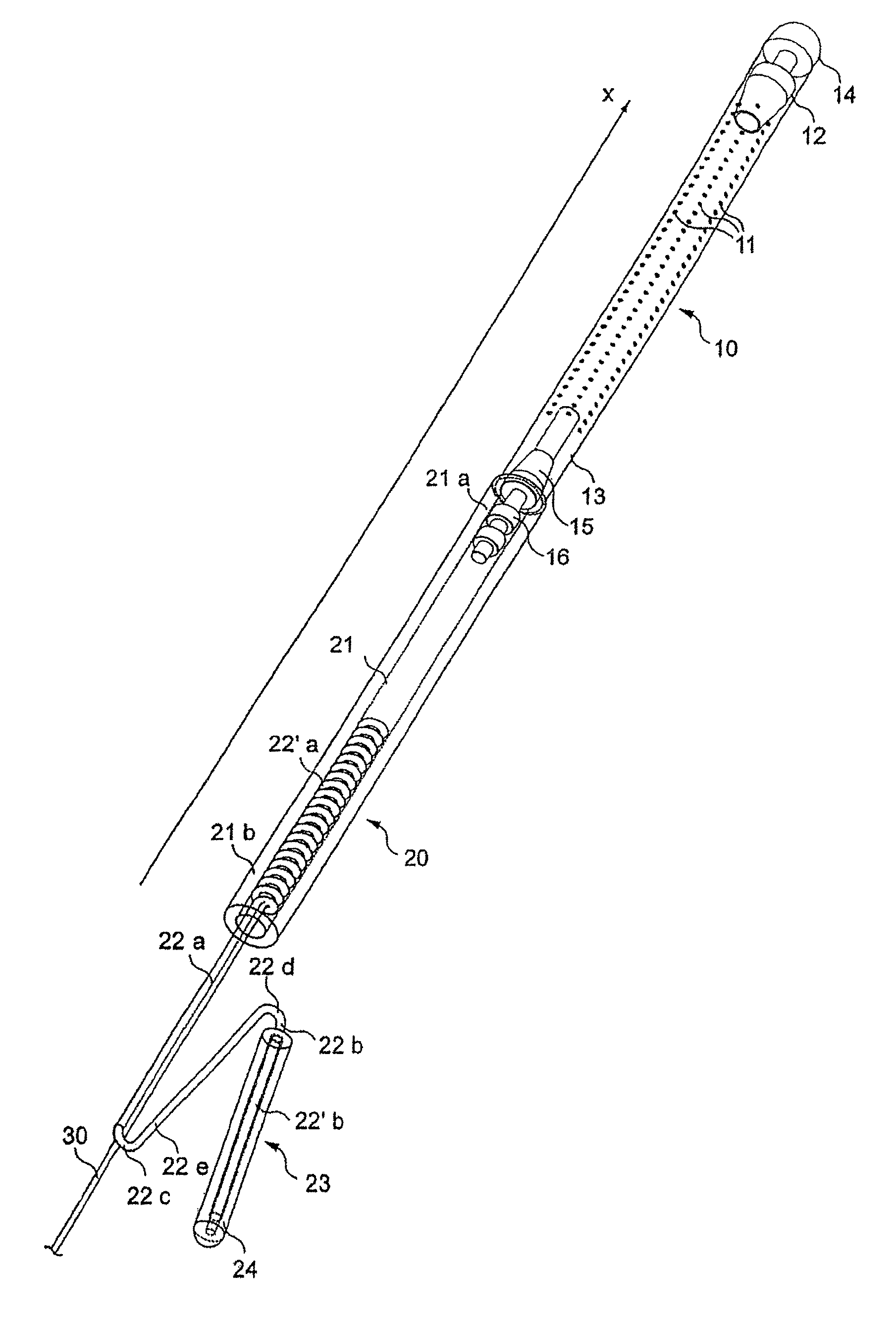
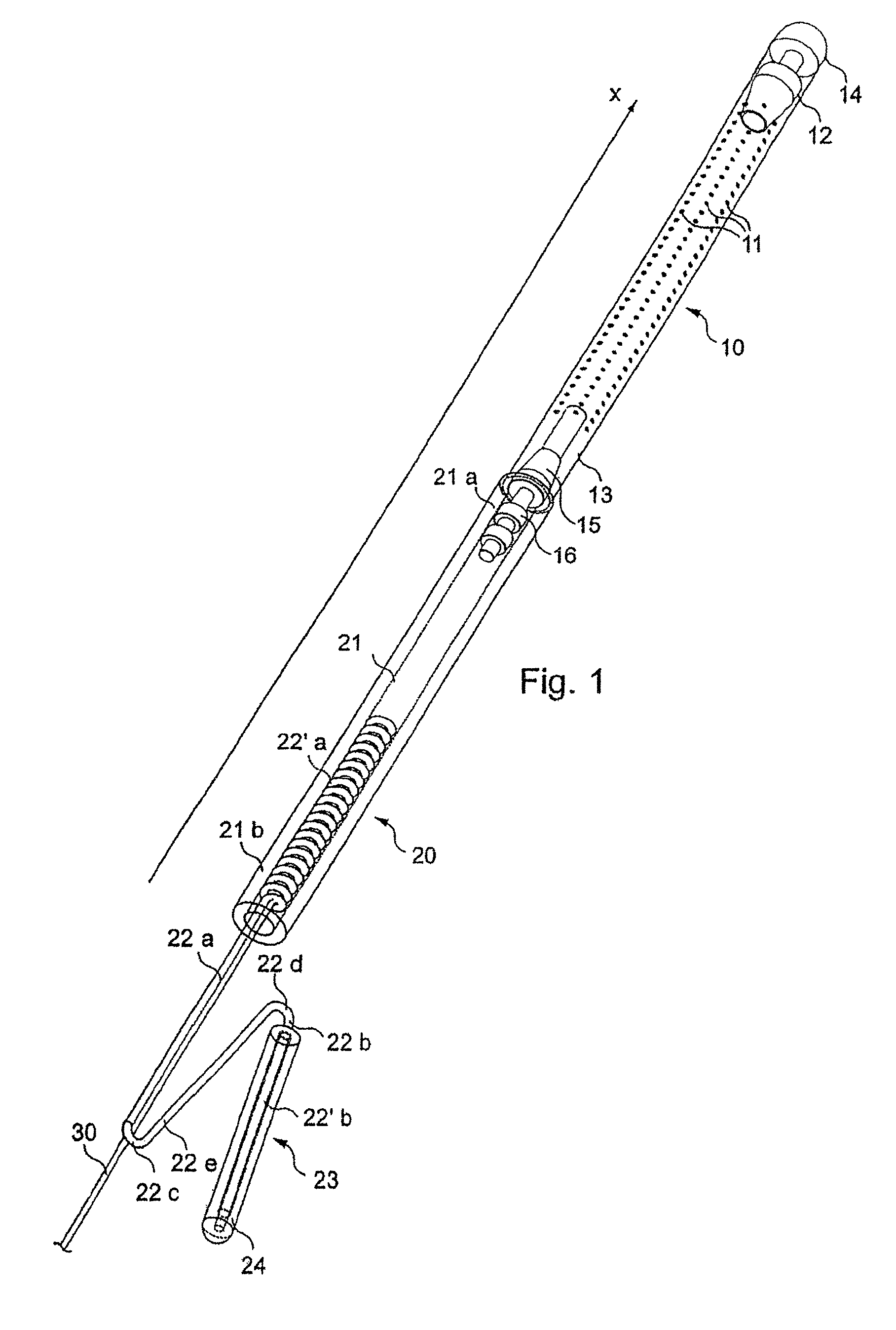
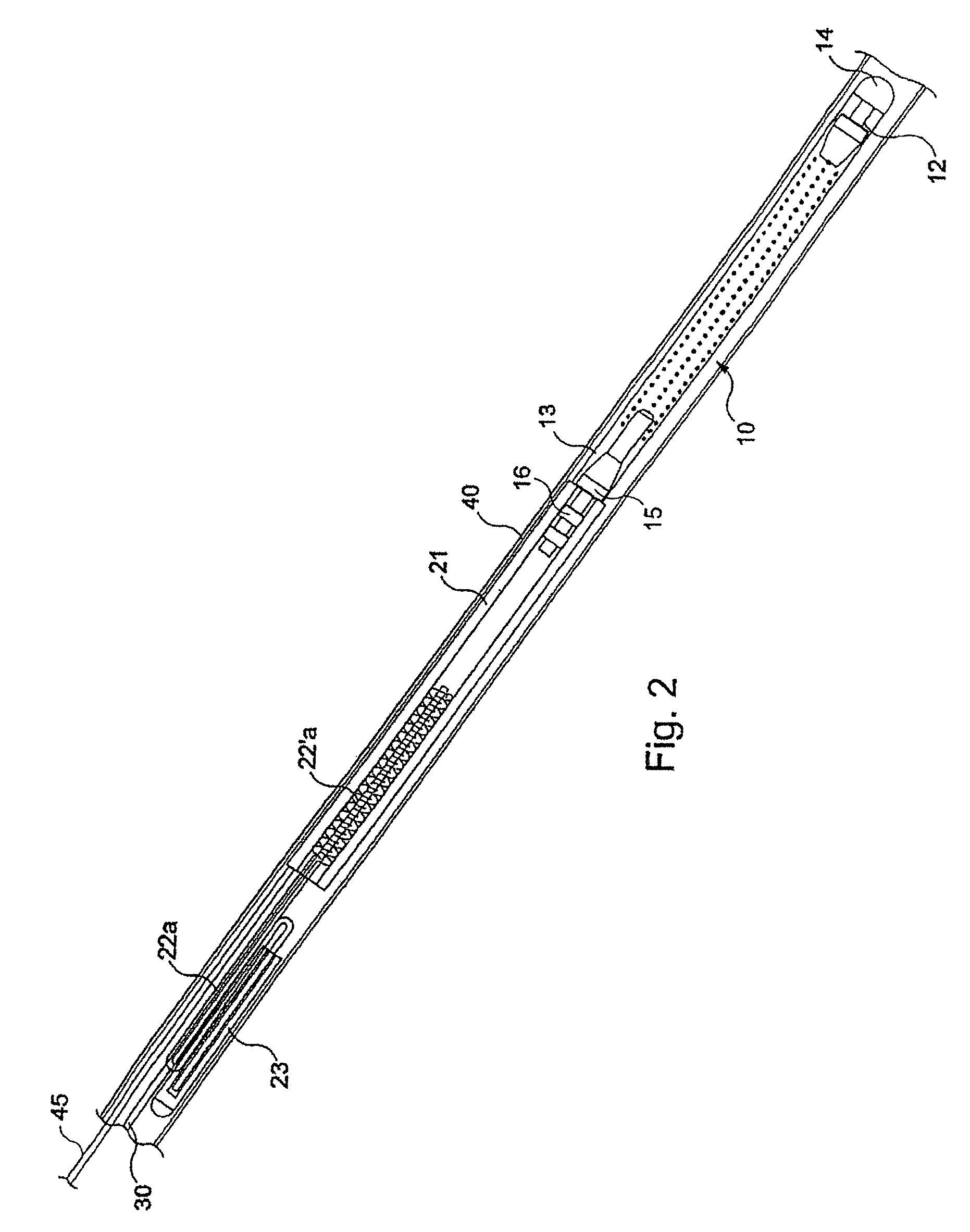
[0038]As shown in FIG. 1, the recoverable intra-uterine system comprises firstly a housing 10 intended to be placed in the uterus.

[0039]This housing 10 is intended to be placed in the uterine cavity for a period between a few hours and a few days with a view to pre-implantation development of an embryo in vivo.

[0040]To this end, the housing 10 is adapted to contain an embryo, male and / or female gametes, a fertilized ovocyte, an unfertilized ovum or a combination of these various elements.

[0041]This housing 10 can be produced in silicone and provided with a series of perforations 11 in its wall enabling interaction between the interior of the housing and the exterior medium in which the housing 10 is placed, that is to say the uterine medium.

[0042]As clearly shown in FIG. 1, this housing 10 is of elongate shape along an axis X.

[0043]In this embodiment, the housing 10 consists of an elongate cylindrical tube.

[0044]By way of nonlimiting example, the length of the housing in the directi...


PUM


Abstract

The recoverable intra-uterine system comprises a housing capable of containing one or a plurality of elements selected from among the group comprising an embryo, male and / or female gametes, a fertilized oocyte, and unfertilized ovum and a combination of these elements, the housing having along an axis a distal end and a proximal end, and a device for holding the recoverable intra-uterine device in the uterus. The holding device is arranged at the proximal end of the housing and includes at least one holding arm in the uterine cavity capable of taking at least two positions: —one free position in which at least one holding arm is separated from the axis; and —a retracted position in which at least one holding arm is substantially parallel to the axis. Use in medically assisted reproduction techniques.

Description

CROSS-REFERENCE TO RELATED APPLICATIONS[0001]This application is the U.S. National Phase Application of International Application No. PCT / IB2007 / 002913, filed Jun. 26, 2007, which claims the benefit of French Application No. FR 0653069, filed Jul. 21, 2006, the disclosures of each of which is hereby incorporated by reference.FIELD OF THE INVENTION[0002]The present invention concerns a recoverable intra-uterine system.[0003]It is generally concerned with stabilizing and retaining in position a recoverable intra-uterine system used in the process of medically assisted procreation.BACKGROUND[0004]Intra-uterine systems that can be implanted and recovered non-invasively have been known for a number of years.[0005]Generally speaking, these systems can be classified into three major families according to their indication or their mode of action. Of these, devices having an anti-conception indication, such as contraceptive IUDs, represent the great majority of cases and constitute the first...

Claims


Application Information

Patent Timeline
IPC IPC(8): A61B17/43A61F6/06A61F6/14
CPCA61B17/43A61B17/435A61F6/144
Inventor MOCK, PASCALBOUCHE, NICOLASLE GOFF, PHILIPPE
Owner ANECOVA SA
Learn More