
Self-stemming cartridge

a self-stemming and cartridge technology, applied in surface mining, ammunition fuzes, explosives, etc., can solve the problems of not seeing widespread adoption, time-consuming operation, dangerous, etc., and achieve the effect of facilitating cracking of hard materials

Active Publication Date: 2013-01-01
BASSETT CARROLL
View PDF23 Cites 11 Cited by
  • Summary
  • Abstract
  • Description
  • Claims
  • Application Information

AI Technical Summary

Benefits of technology

The self-stemming cartridge effectively cracks hard materials by concentrating blast force, enhancing safety and productivity, and reducing collateral damage with a smaller, easily rupturable casing made of materials like cardboard or plastic, allowing for safe and efficient small-scale blasting.

Problems solved by technology

This operation is both time consuming and, in some instances, dangerous.
Several stemming devices have been developed to eliminate this process; however, they have not seen widespread adoption given their cost, lack of effectiveness in stemming the blast hole or because they are bulky and difficult to use.
Furthermore, the device of Gotham does not have a single casing surrounding both the charge and the stemming aspect, and the casing it does have is a metal casing requiring a significant blast force to function.
The blasting device of Holt, however, does not incorporate the charge and the stemming apparatus within a common casing, but incorporates the blasting device in a side opening of the stemming device.

Method used


Image

  • Self-stemming cartridge
  • Self-stemming cartridge
  • Self-stemming cartridge

Examples


Embodiment Construction

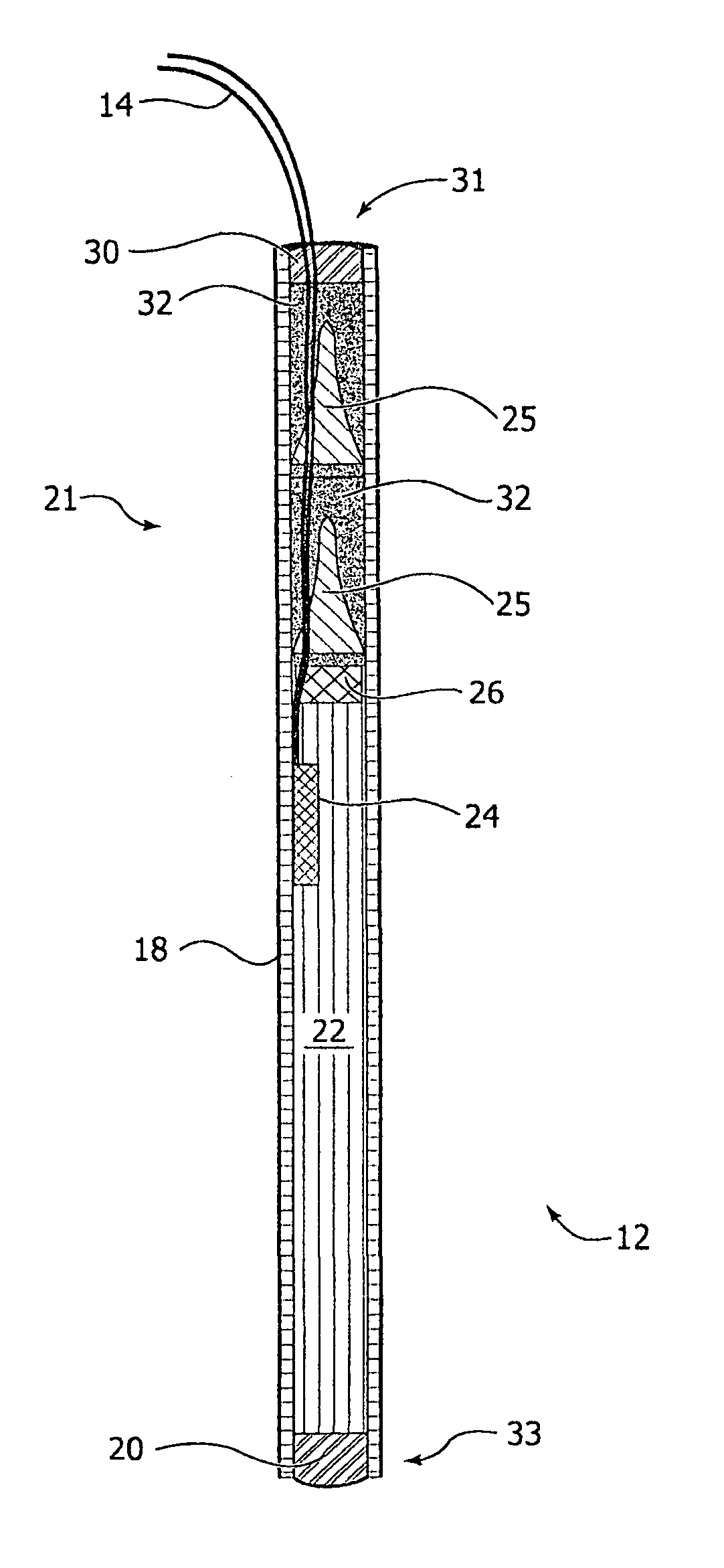
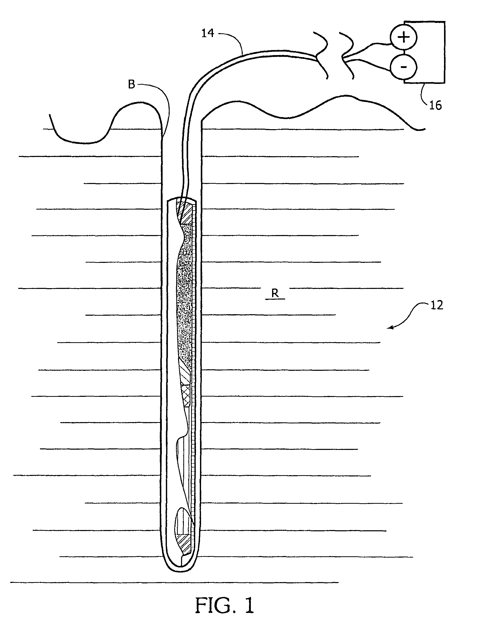
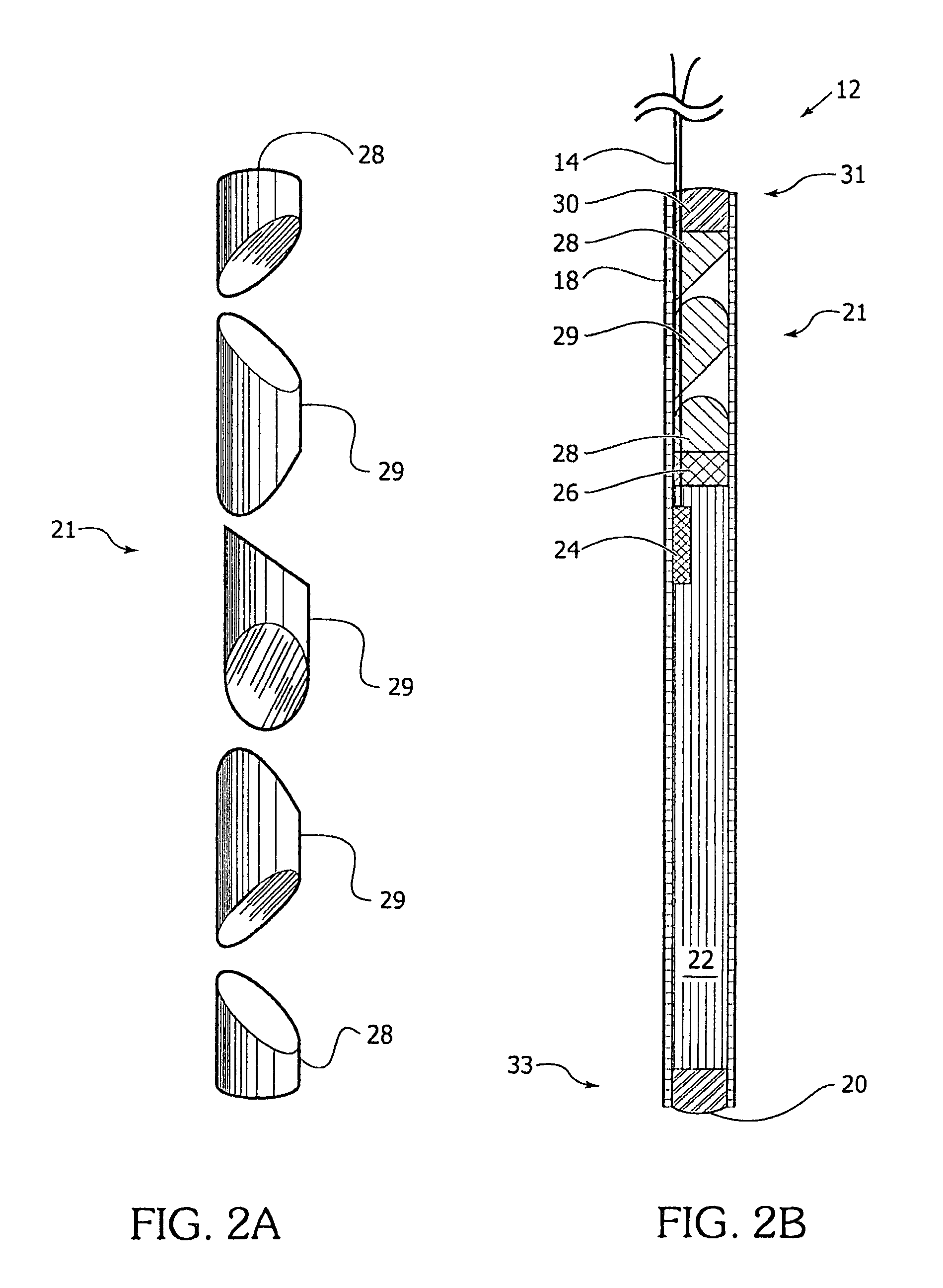
[0024]A self-stemming cartridge (12), as shown in FIGS. 1, 2B, 3, 4, has a cylindrical casing (18) with a first end (33) and a second end (31). The first end (33) is closed. The first end (33) may be closed by crimping which is well known but may also be closed by a plug (20), such as a hot glue plug, as shown. The crimping method of closing the first end (33) may be preferred for automated manufacturing. The cylindrical casing (18) encloses an accelerant (22) disposed adjacent the first end (33), and at least one stemming mechanism (21) disposed between the accelerant (22) and the second end (31). A fuse (14 or 14′) extends from the accelerant (22) out of the second end (31) of the cylindrical casing (18).

[0025]The explosive material, or accelerant, is preferably a propellant, such as smokeless powders, black powders, or the like. Although high explosives are not the preferred explosive material, the present invention is seen to encompass embodiments which contain such explosives. ...


PUM


Abstract

A cylindrical casing (18) has first and second ends (33 and 31), the first end (33) being closed. The casing (18) encloses an accelerant (22) disposed adjacent the first end (33), at least one stemming mechanism (21), and a fuse (14 or 14′) extending from the accelerant (22) out of the second end (31) of the cylindrical casing (18). The cartridge (12) is made of a rupturable cylindrical casing (18) with accelerant (22) and self-stemming mechanism (22) inserted therein. A method of breaking hard (R) materials involves detonating a self-stemming cartridge (12) disposed in a borehole (B).

Description

RELATED APPLICATIONS[0001]This application claims the benefit of U.S. Provisional Application Ser. No. 60 / 862,124 entitled “SELF-STEMMING CARTRIDGE” filed on 19 Oct. 2006, the contents of which are incorporated herein by reference in its entirety.BACKGROUND OF THE INVENTION[0002]Historically when blasting techniques are used to crack rock and concrete, an explosive charge is placed in a drilled hole followed by a stemming operation to help retain the force of detonation within the borehole. The stemming operation tends to involve packing the borehole above the explosive charge with some material, such as gravel, clay, and mud, to prevent the explosive force from simply being vented out of the borehole without cracking the rock. This operation is both time consuming and, in some instances, dangerous. Several stemming devices have been developed to eliminate this process; however, they have not seen widespread adoption given their cost, lack of effectiveness in stemming the blast hole...

Claims


Application Information

Patent Timeline
Patent Type & Authority Patents(United States)
IPC IPC(8): F42D1/22F42B3/04
CPCF42B3/087F42D1/20F42D1/22
Inventor BASSETT, CARROLL
Owner BASSETT CARROLL
Learn More