Method and system for providing an improved hard bias structure

a hard bias structure and hard bias technology, applied in the field of providing an improved hard bias structure, can solve the problems of changing the final stripe height of the magnetoresistive sensor, and affecting the ability of the conventional hard bias structure to adequately bias the conventional magnetoresistive sensor

Inactive Publication Date: 2013-01-01
WESTERN DIGITAL TECH INC
View PDF18 Cites 150 Cited by
  • Summary
  • Abstract
  • Description
  • Claims
  • Application Information

AI Technical Summary

Benefits of technology

[0009]A method and system for providing a magnetic transducer is described. The method and system include defining a magnetoresistive sensor in a track width direction and providing hard bias material(s). A first portion of the hard bias material(s) is substantially adjacent to the magnetoresistive sensor in the track width direction. The method and system also include providing at least one sacrificial capping layer on a second portion of the hard bias material(s). The sacrificial capping layer(s) have a first height in a stripe height direction substantially perpendicular to the track width direction. The method and system also include providing a mask for defining a stripe height of the magnetoresistive sensor in the stripe height direction. The mask covers at least a portion of the magnetoresistive sensor and has a second height in the stripe height direction. The second height is less than the first height. The method and system also include defining the stripe height of the magnetoresistive sensor while the mask covers the at least the portion of the magnetoresistive sensor. The sacrificial capping layer(s) are configured to prevent removal of the second portion of the hard bias material(s) during the step of defining the stripe height.

Problems solved by technology

In addition, lapping or other processing may change the final stripe height of the magnetoresistive sensor.
This topology is transferred to the conventional hard bias structure, which gives rise to magnetic instabilities in the conventional hard bias structure.
Therefore the conventional hard bias structure's ability to adequately bias the conventional magnetoresistive sensor may still be compromised.
Thus, the signal-to-noise ratio of the conventional read transducer may be adversely affected.

Method used


Image

  • Method and system for providing an improved hard bias structure
  • Method and system for providing an improved hard bias structure
  • Method and system for providing an improved hard bias structure

Examples


Embodiment Construction

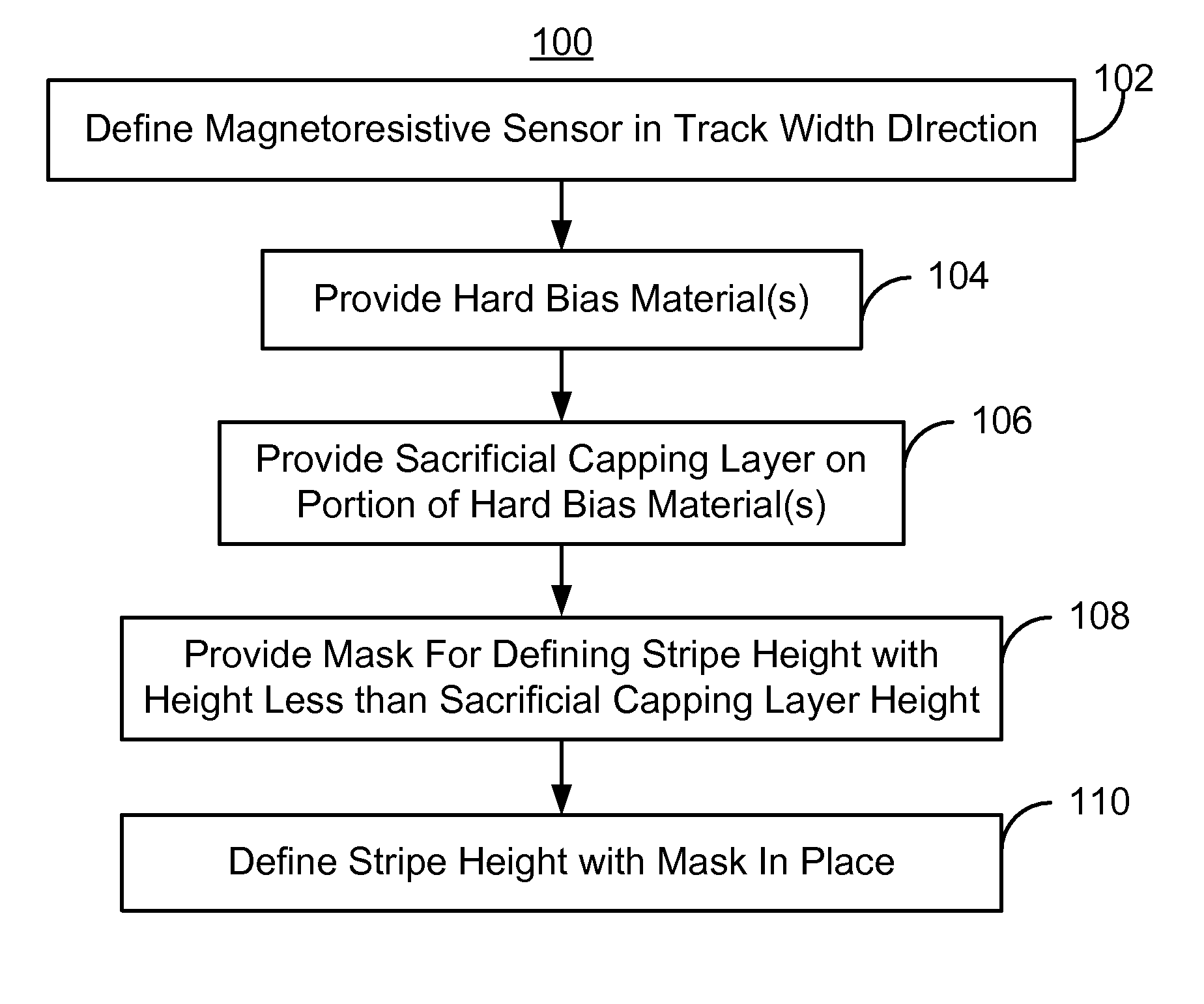
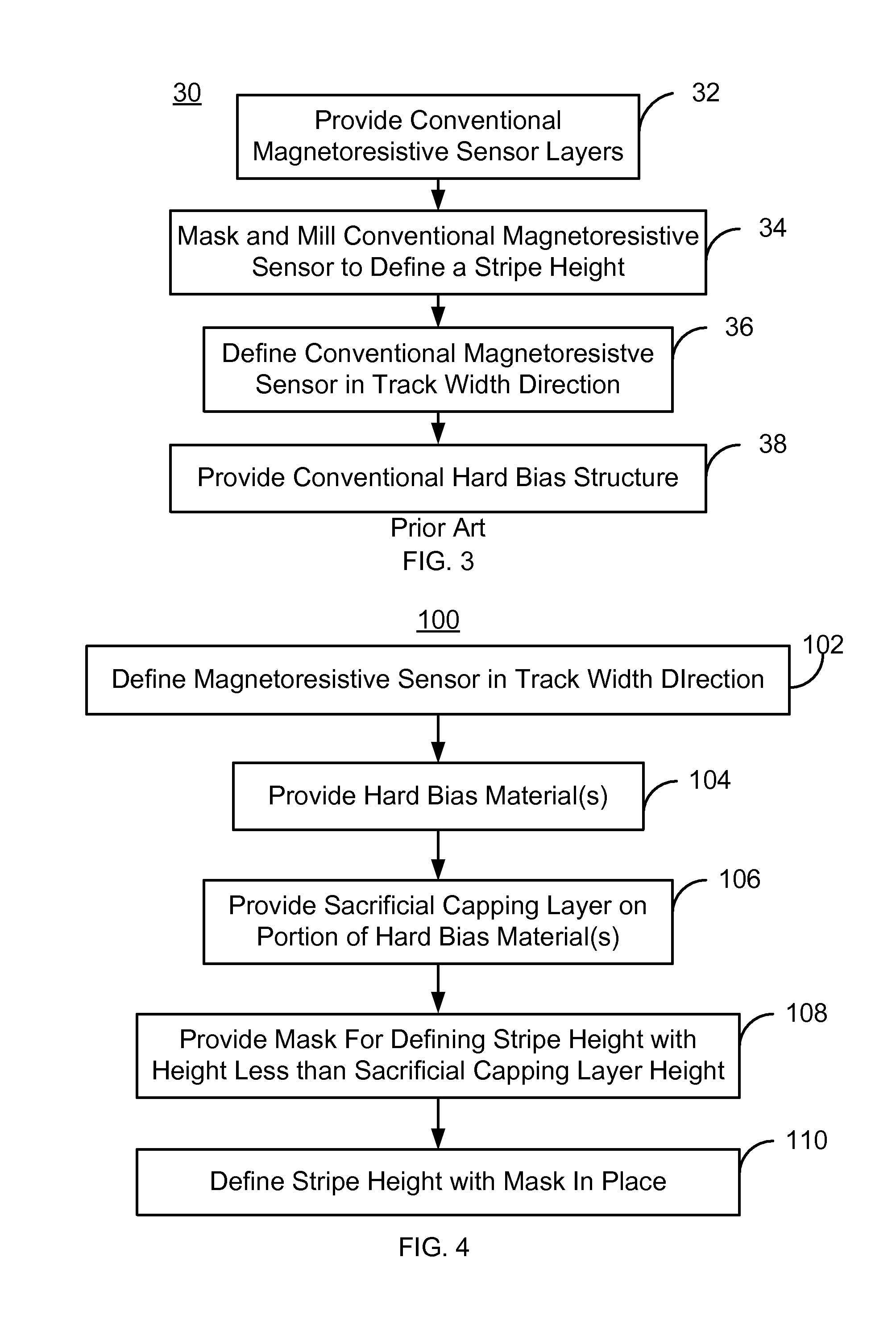
[0017]FIG. 4 is a flow chart of an exemplary embodiment of a method 100 for fabricating a magnetic transducer, particularly a read transducer. For simplicity, some steps may be omitted or combined with other steps. The method 100 also may commence after formation of other structures of the read transducer. The method 100 is also described in the context of providing a single magnetic transducer. However, the method 100 may be used to fabricate multiple structures at substantially the same time. The method 100 is also described in the context of particular layers. However, in some embodiments, such layers may include sub-layer(s). The method 100 also commences after the magnetoresistive stack has been provided, preferably by blanket depositing the layers. For example, an AFM layer, a pinned layer, a nonmagnetic spacer layer, and a free layer may have been deposited. The pinned layer may be a synthetic antiferromagnetic (SAF) layer including magnetically coupled ferromagnetic sublayer...


PUM

PropertyMeasurementUnit
angleaaaaaaaaaa
angleaaaaaaaaaa
thicknessaaaaaaaaaa

Abstract

A method and system for providing a magnetic transducer is described. The method and system define a magnetoresistive sensor in a track width direction, provide hard bias material(s) adjacent to the sensor in the track width direction, and provide sacrificial capping layer(s) on a portion of the hard bias material(s). The sacrificial capping layer(s) have a first height in a stripe height direction. The method and system also provide a mask for defining a stripe height of the sensor. The mask covers at least part of the sensor and has a second height in the stripe height direction. The second height is less than the first height. The method and system define the stripe height of the sensor while the mask covers the sensor. The sacrificial capping layer(s) are configured to prevent removal of the portion of the hard bias material(s) while the stripe height is defined.

Description

BACKGROUND[0001]FIG. 1 depicts a conventional method 10 for forming a read transducer. The conventional method 10 commences after structures in the conventional read transducer have been formed. For example, shield(s), write transducer(s) or other structures may have been fabricated. A conventional magnetoresistive sensor that is defined in the track width direction and conventional hard bias structures are provided, via step 12. Step 12 includes formation of the conventional magnetoresistive stack. A conventional antiferromagnetic (AFM) layer, a conventional pinned layer, a conventional nonmagnetic spacer layer, and a conventional free layer may have been deposited. In addition, the layers may have been masked and ion milled in the track width direction to define the sensor in this direction using step 12. The track width direction is parallel to the air-bearing surface (ABS) and generally perpendicular to the layers of the magnetoresistive stack. Further, a thin insulating layer o...

Claims


Application Information

Patent Timeline
Patent Type & Authority Patents(United States)
IPC IPC(8): C23C14/34
CPCG11B5/3163G11B5/3932
Inventor LI, GUANXIONGXIANG, XIAOHAIMAO, MINGPAKALA, MAHENDRA
Owner WESTERN DIGITAL TECH INC
Why Eureka
Try Eureka