
Turbine inlet air system

a technology of turbines and air systems, applied in the direction of auxillary pretreatment, separation process, filtration separation, etc., can solve the problems of clogging of known air filters, reducing the life expectancy and performance of equipment, and damaging compressor blades and other types of power plant equipmen

Active Publication Date: 2013-01-08
PARKER INTANGIBLES LLC
View PDF23 Cites 3 Cited by
  • Summary
  • Abstract
  • Description
  • Claims
  • Application Information

AI Technical Summary

Benefits of technology

The patent describes a method to prevent small droplets from getting into a gas turbine engine's filter. The method involves using a device called a coalescer to make the droplets larger, eliminating them from the air flow. This results in a cleaner, more efficient air flow for the engine.

Problems solved by technology

Inlet air filtration systems thus may be used upstream of the compressor, impure air laden with dust particles, salt, and other contaminants may damage the compressor blades and other types of power plant equipment via corrosion, erosion, and the like.
Such damage may reduce the life expectancy and performance of the equipment.
Known air filters, however, may be clogged by environmental conditions such as fog, rain, snow, and the like.
Such clogging may reduce filtration and cooling efficiency while increasing the overall pressure drop.
Inlet air pressure loss also can result in the loss of power output for the gas turbine engine as a whole.
Small water droplets such as fog or fine mist may cause such filter failure due to an increased pressure loss across the filter caused by clogging and the like.
The potential for clogging is particularly true with final fitters such as pulse cartridges and similar devices.
Standard water or mist removal systems may not be sufficiently efficient to remove such small water droplets before contact with the filters and potential damage thereto.

Method used


Image

  • Turbine inlet air system
  • Turbine inlet air system
  • Turbine inlet air system

Examples


Embodiment Construction

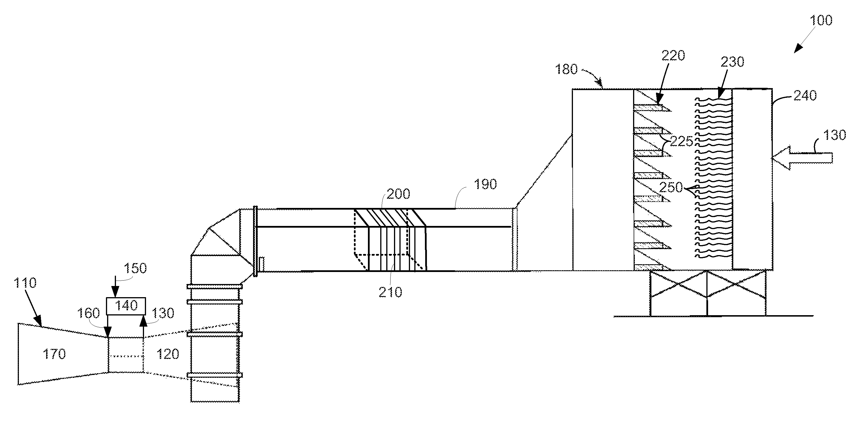
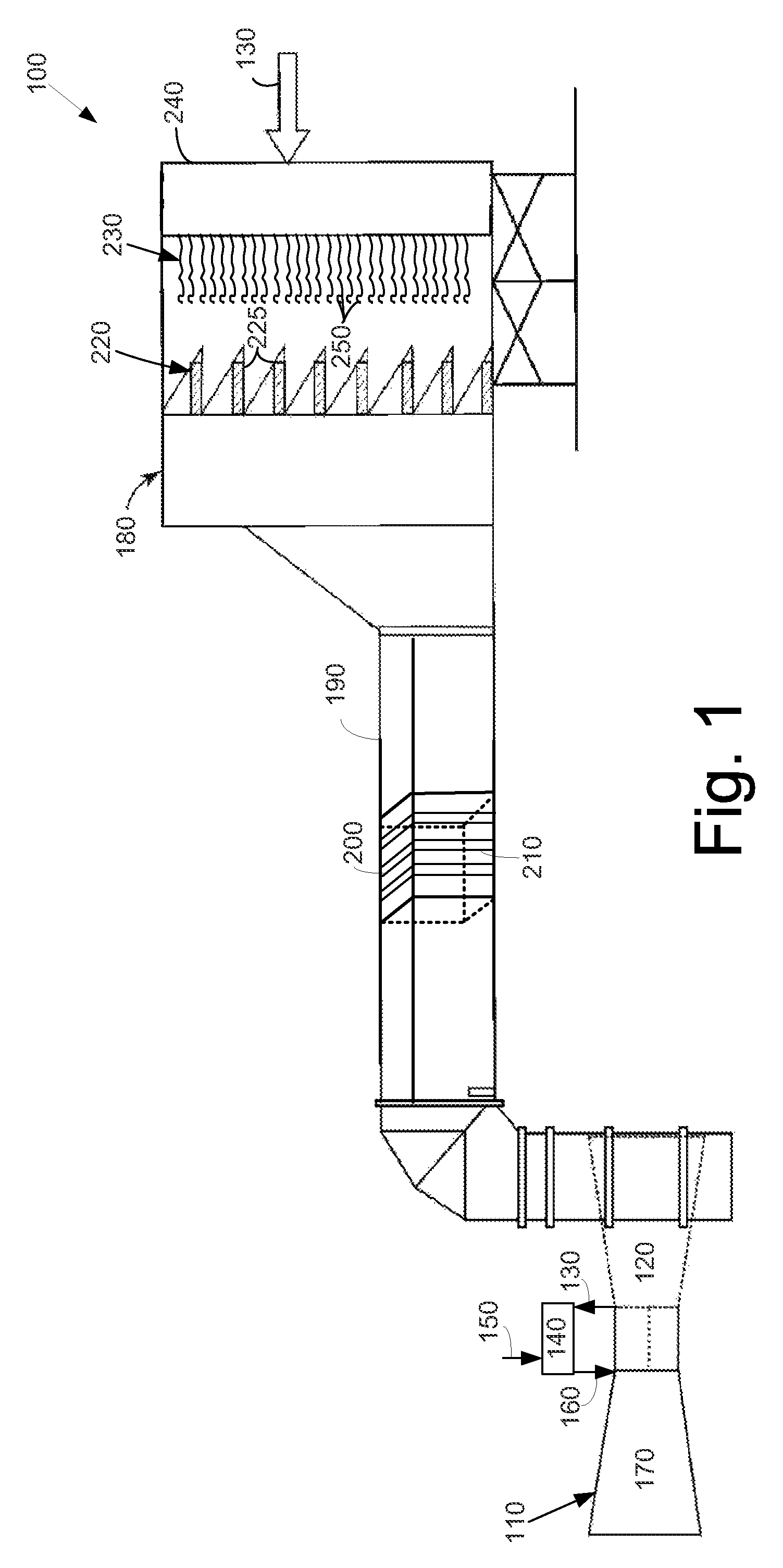
[0012]Referring now to the drawings, in which like numerals refer to like elements throughout the several views, FIG. 1 shows an example of a turbine inlet air system 100 as may be described herein. The turbine inlet air system 100 may be used with a gas turbine engine 110. As is known, the gas turbine engine 110 may include a compressor 120. The compressor 120 compresses an incoming flow of air 130. The compressor 120 delivers the compressed flow of air 130 to a combustor 140. The combustor 140 mixes the compressed flow of air 130 with a compressed flow of fuel 150 and ignites the mixture to create a flow of combustion gasses 160. The flow of combustion gases 160 is in turn delivered to a turbine 170. The flow of combustion gases 160 drives the turbine 170 so as to produce mechanical work. The gas turbine engine 110 may use natural gas, various types of syngas, and / or other types of fuels. The gas turbine engine 110 may be any one of a number of different gas turbine engines offere...


PUM

PropertyMeasurementUnit
flexibleaaaaaaaaaa
pressure dropaaaaaaaaaa
pressureaaaaaaaaaa

Abstract

The present application provides a turbine inlet air system. The turbine inlet air system may include a small droplet coalescer, a moisture eliminator positioned about the small droplet coalescer, and a filter downstream of the small droplet coalescer and the moisture eliminator.

Description

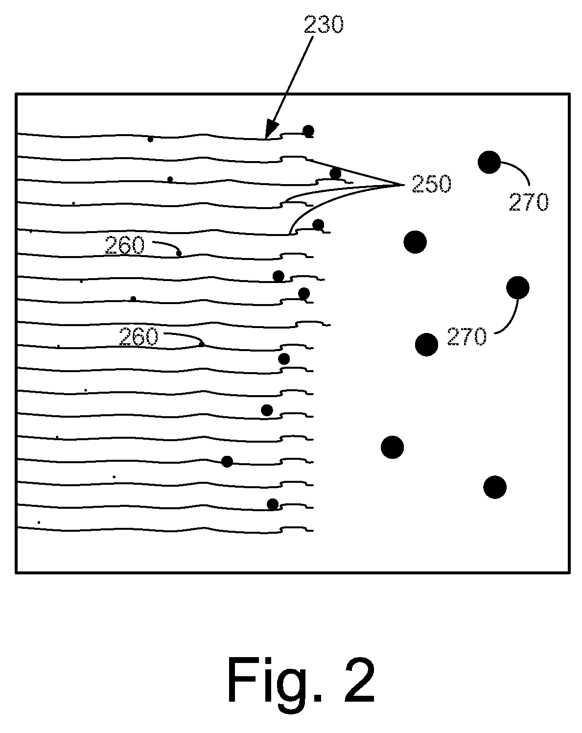
TECHNICAL FIELD[0001]The present application relates generally to gas turbine engines and more particularly relates to a turbine inlet air system having a coalescer using multiple telltales to agglomerate fine mist or small water droplets into larger droplets.BACKGROUND OF THE INVENTION[0002]Power generation equipment, such as a gas turbine engine, uses a large supply of intake air to support the combustion process. Inlet air filtration systems thus may be used upstream of the compressor, impure air laden with dust particles, salt, and other contaminants may damage the compressor blades and other types of power plant equipment via corrosion, erosion, and the like. Such damage may reduce the life expectancy and performance of the equipment. To avoid this problem, the inlet air generally passes through a series of filters to remove the contaminants. Known air filters, however, may be clogged by environmental conditions such as fog, rain, snow, and the like. Such clogging may reduce fi...

Claims


Application Information

Patent Timeline
Patent Type & Authority Patents(United States)
IPC IPC(8): B01D50/00
CPCF01D25/32F02C7/05F02C7/052F02C7/055
Inventor JARRIER, ETIENNE RENE
Owner PARKER INTANGIBLES LLC
Learn More