Adsorption drying apparatus and adsorption drying method

a drying apparatus and adsorption technology, applied in the direction of electrostatic separation, emergency control system, electric supply techniques, etc., can solve the problems of insufficient regeneration capacity within the drying sector, minor heat available for regenerating, disadvantageous methods according to the prior art, etc., to achieve the effect of reducing the relative humidity of the gas, preventing or reducing damage to the adsorption material, and long li

Active Publication Date: 2013-01-08
KAESER KOMPRESSOREN SE
View PDF10 Cites 34 Cited by
  • Summary
  • Abstract
  • Description
  • Claims
  • Application Information

AI Technical Summary

Benefits of technology

[0024]A further advantage of the invention is that the gas stream temperature is raised by the pressure-increasing device. This lowers the relative humidity of the gas so that water drops, which might be still present, evaporate. Damage to the adsorption material may thus be prevented or reduced so that comparatively long lifetimes can be achieved, particularly as compared to the partial stream method.
[0025]The term “drying” may be understood in a restricting way to the extent that water has to be removed from an air stream or gas stream. In general, however, “drying” should be understood as the removal of an adsorbable and / or condensable component from an air stream or gas stream.
[0026]An adsorption chamber or “drying drum,” as generally usual and known in air conditioning technology or compressed air drying in the partial stream method, can be used (e.g., see U.S. Pat. No. 4,391,667).
[0027]Preferably, the drying drum, for example, is made of a thin carrier material of plane and corrugated foils, which defines a structure of preferably parallel conduits and onto which an adsorbent, e.g. silica gel, is fixed which is chemically bound, for example. Depending on the size of the drying drum, metal sheets (spokes) can be fixed around an axis of rotation which extend from the inside radially outwardly along the axis of rotation (drum axis). A comparatively high stability of the drying drum is thus achieved. In the segments which are created by forming of the spokes, blocks having the conduit structures described above can be fixed. Also, two or more blocks or rows of blocks may be arranged one behind the other, so that drying drums of a greater length may be provided or the length of the drying drum varied, which increases the efficiency of the drying process.
[0028]Preferably, the conduits are formed to be smaller than the edges of the corresponding zones, so that an adsorption conduit cannot be in concurrent communication with two zones delimited by the edges.
[0029]The adsorption chamber can be supported to be rotatable within an adsorption container, which preferably also comprises at least in part the feeding and discharging lines. Such feeding and discharging lines are simple to manufacture and robust.

Problems solved by technology

The method according to the prior art is found to be disadvantageous.
However, only a minor part of the heat is available for the regenerating, since only the mentioned partial stream is conducted through the regeneration sector.
In general, the regeneration capacity within the drying sector is often not sufficient, in particular when larger amounts of humidity have to be adsorbed in the adsorption chamber 11 due to low pressures or high temperatures of cooling media of the heat exchangers used (secondary cooler 3 and regeneration cooler 13).
In sum, the method according to the prior art offers a comparatively low operational safety as far as unfavorable conditions are concerned.
Moreover, the ejector 15 is of a comparatively low energy-efficiency.
In particular, when a high regeneration flow has to be achieved, a comparatively high pressure loss of the main stream is required to suck in the regeneration stream.
At deviating operating pressures and volume flows, more unfavorable regeneration stream proportions occur.
When such drops impact an adsorption material in the adsorption chamber 11, sudden heat developments and material damages arise.
The lifetime of the adsorption material is thus comparatively limited.
A problem in this case is that a leakage stream occurs as a part of the humid regeneration stream from the regeneration inlet chamber 6 and the regeneration outlet chamber 7 into the drying outlet chamber 9 and / or drying inlet chamber 8, which exhibit lower pressures in the known methods.
During rotation, such seals are exposed to high loads leading to rapid wear and therefore costs.
The realization of the latter method is comparatively laborious, with the comparatively high differential pressures within the adsorption chamber putting extremely high demands on the sealing at a drum surface of the adsorption chamber and the mechanical stability of a material from which the adsorption chamber is made.
Especially, a high differential pressure between a regeneration zone and the interspace suction involves the risk of high leakage streams which can strongly affect the efficiency of the method.
In a first group, only a partial stream is used for regeneration, which reduces the efficiency for the reasons explained above.
In a second group, the entire stream is used for regeneration, which, however, either leads to a leakage and hence a lower drying degree that can be achieved, or involves a comparatively high constructional expenditure.

Method used


Image

  • Adsorption drying apparatus and adsorption drying method
  • Adsorption drying apparatus and adsorption drying method
  • Adsorption drying apparatus and adsorption drying method

Examples


Embodiment Construction

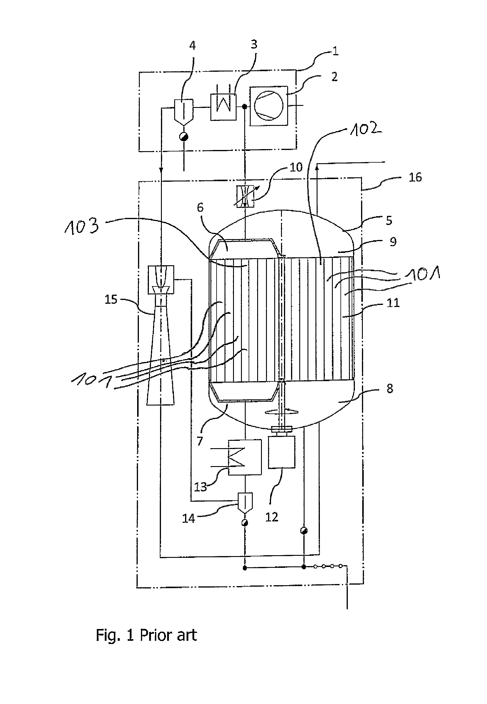
[0088]The adsorption drying apparatus according to FIG. 1 (prior art) was already described above.

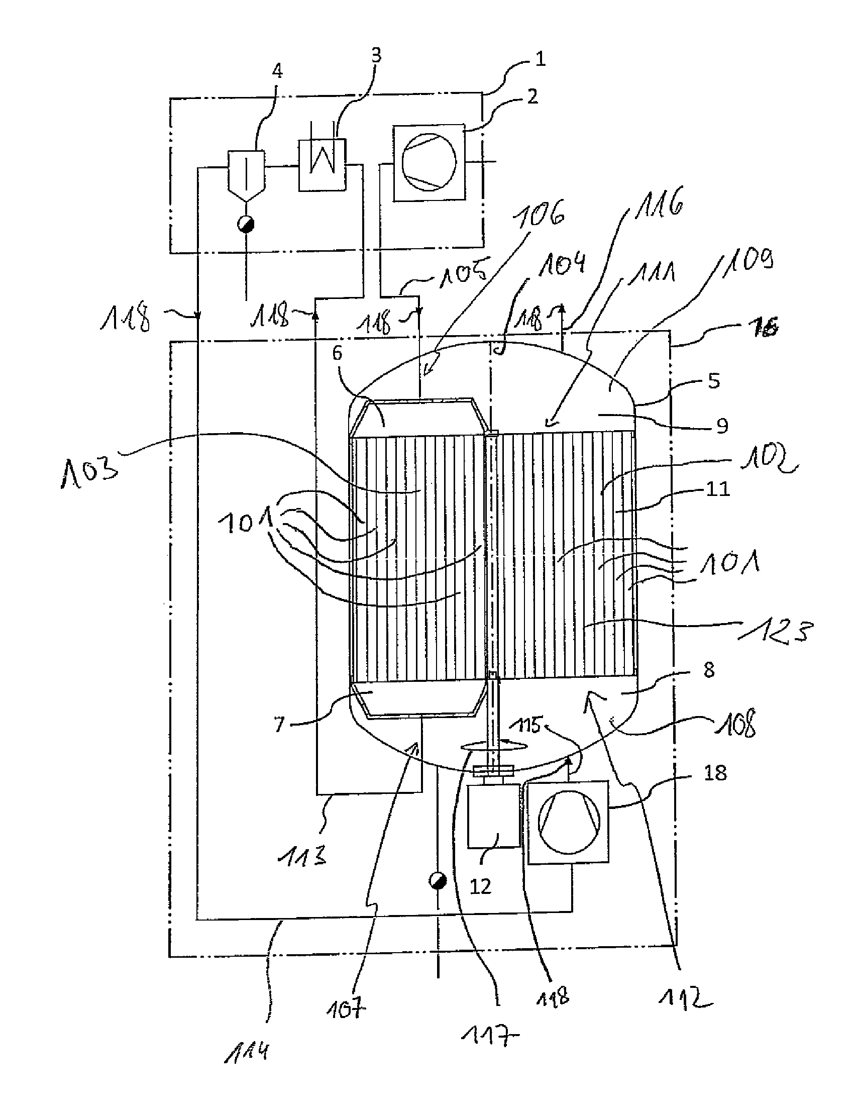
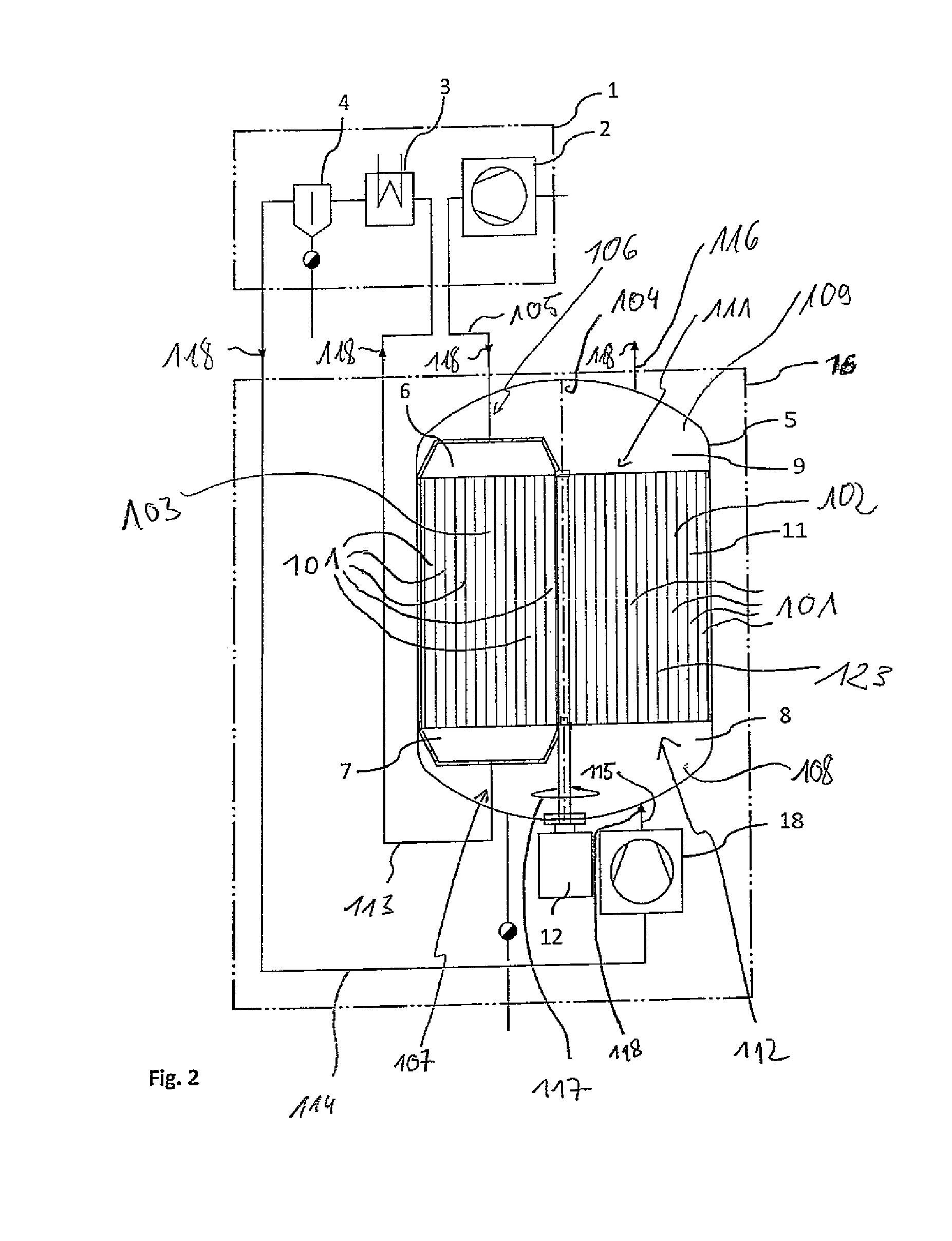
[0089]FIG. 2 shows an adsorption drying apparatus according to an embodiment of the invention in a schematic representation. An adsorption material 123 is located in an adsorption chamber 11 supported within an adsorption container 5 to be rotatable about an axis of rotation 104. The adsorption chamber 11 comprises a plurality of preferably parallel adsorption conduits 101 through which the gas to be dried can be conducted.

[0090]Via a line 105 the gas to be dried, which was compressed in a compressor block 2 of the input compressor 1, can be fed to a regeneration inlet chamber 6, which forms at least in part a first feeding line 106. The regeneration inlet chamber 6 and the first feeding line 106 are arranged at a first end 111 of the adsorption chamber 11. In this case, the entire gas stream exiting the compressor block 2 is conducted to the regeneration inlet chamber 6 via the line 10...


PUM

PropertyMeasurementUnit
pressureaaaaaaaaaa
pressureaaaaaaaaaa
speedaaaaaaaaaa

Abstract

An adsorption drying apparatus, in particular for drying a compressed gas, includes an adsorption chamber (11) having a plurality of adsorption conduits (101) containing an adsorption material (123), a first feeding line (106) and a first discharging line (109) disposed at a first end (111) of the adsorption chamber (11), and a second feeding line (108) and a second discharging line (107) disposed at a second end (112) of the adsorption chamber (11). The adsorption chamber (11) is rotatable with respect to the feeding and discharging lines (106, 107, 108, 109) so that the adsorption conduits may be fluidically connected in temporal alternation, wherein the gas is dried in a drying sector (102), and the adsorption material (123) is regenerated in the regeneration sector (103). The first feeding line (106) is configured such that the gas stream to be dried may be fed to the regeneration sector (103) as a full flow.

Description

BACKGROUND OF THE INVENTION[0001]The invention relates to an adsorption drying apparatus as well as an adsorption drying method, particularly for drying compressed gases.[0002]For drying gases, adsorption methods are frequently used. The dehumidification of compressed air, nitrogen, natural gas or gases from chemical production processes should be mentioned by way of example. Apart from methods using two or more separate adsorption containers which run through a drying cycle and a regeneration cycle in mutual alternation, there are methods working on a rotating adsorbent, in which the adsorbent is fixed within a drum and continuously moved through a sector in which it is regenerated (regeneration sector), and a sector in which it is used for drying (drying sector). On the front sides of the adsorbent, chambers are present through which the various gas flows are passed through the sectors. The sectors are each formed by the parts of a drum situated in the zones defined by the chamber...

Claims


Application Information

Patent Timeline
Patent Type & Authority Patents(United States)
IPC IPC(8): B01D53/06B01D53/26
CPCB01D53/06B01D53/261B01D2257/80
Inventor FREDENHAGEN, ANDREASMARTIN, RENEFEISTHAUER, MICHAELROHDENBURG, MICHAEL
Owner KAESER KOMPRESSOREN SE
Why Eureka
Try Eureka