Method for applying a reinforced composite material to a structural member

a technology of reinforced composite materials and structural elements, applied in the direction of structural elements, paper/cardboard containers, lamination, etc., to achieve the effect of reducing the supporting function of such elements, increasing the working load of structures, and altering the structural form

Inactive Publication Date: 2013-01-08
AL EMRANI MOHAMMAD +2
View PDF3 Cites 3 Cited by
  • Summary
  • Abstract
  • Description
  • Claims
  • Application Information

AI Technical Summary

Benefits of technology

[0015]This method allows pre-stressed reinforced composite materials having a non-uniform pre-stressing to be used for the internal and / or external reinforcement of existing structures or for the reinforcement of structures under construction without having to use permanent mechanical anchors and thus avoiding the above-mentioned problems associated with permanent mechanical anchors. The pre-stressing process is simple, reliable and cost-effective and takes a short time, which limits disruptions and delays while repair or reinforcement work is taking place, such as disruptions and delays in the traffic flow over a heavily traficated bridge for example, which can otherwise present a major problem when using conventional methods.
[0016]Very high pre-stressing forces (up to 1500 MPa) can be applied to the reinforced composite material without concentrating interfacial stresses along the adhesive layer between the structural member and the reinforced composite material at the ends of the reinforced composite material. The reinforced structural member will be less prone to slip deformations and environmental attacks due to the lower state of stress in the adhesive layer, which improves the safety and performance of the strengthening system and increases its useful lifetime.
[0017]Finite element analysis of this method has confirmed that the magnitude of critical shear and peeling stresses at the ends of a pre-stressed reinforced composite material can be reduced by a factor of ten as compared to conventional methods in which an reinforced composite material is adhered to a structural member in uniformly pre-stressed state. Shear and peeling stresses at the ends of a pre-stressed reinforced composite material may in fact be eliminated all together by leaving part of the laminate at the end stress-free.
[0033]According to an embodiment of the invention the reinforced composite material is a carbon fibre reinforced polymer (CFRP) in fabric, pre-impregnated or pre-cured laminate form for example. The favourable characteristics of CFRP laminates have caused a rapid increase in the quantity and quality of CFRP material being produced and a reduction in the cost of CFRP material is therefore forecasted.
[0035]The methods according to any embodiment of the invention are intended for use particularly, but not exclusively in the aerospace, automotive, marine, and construction industries. The method may be used to increase the working load of a structure or to alter its structural form by removing supporting elements such as pillars, or by reducing the supporting function of such elements. It may be used to strengthen elements at risk from fatigue stress, increase rigidity, compensate damage to the support system of a structure or to renovate an existing construction, or effect post-construction reinforcement in the event of faulty calculation or execution of a particular construction.

Problems solved by technology

The pre-stressing process is simple, reliable and cost-effective and takes a short time, which limits disruptions and delays while repair or reinforcement work is taking place, such as disruptions and delays in the traffic flow over a heavily traficated bridge for example, which can otherwise present a major problem when using conventional methods.

Method used


Image

  • Method for applying a reinforced composite material to a structural member
  • Method for applying a reinforced composite material to a structural member
  • Method for applying a reinforced composite material to a structural member

Examples


Embodiment Construction

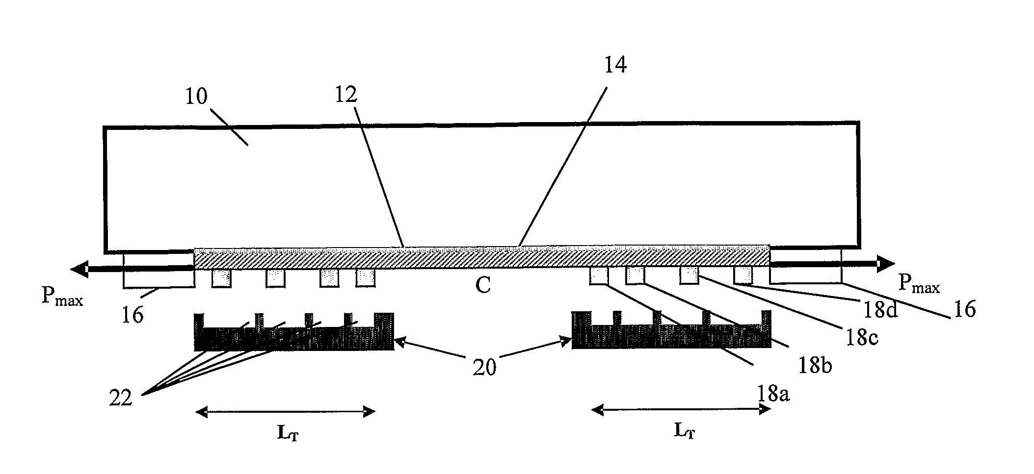
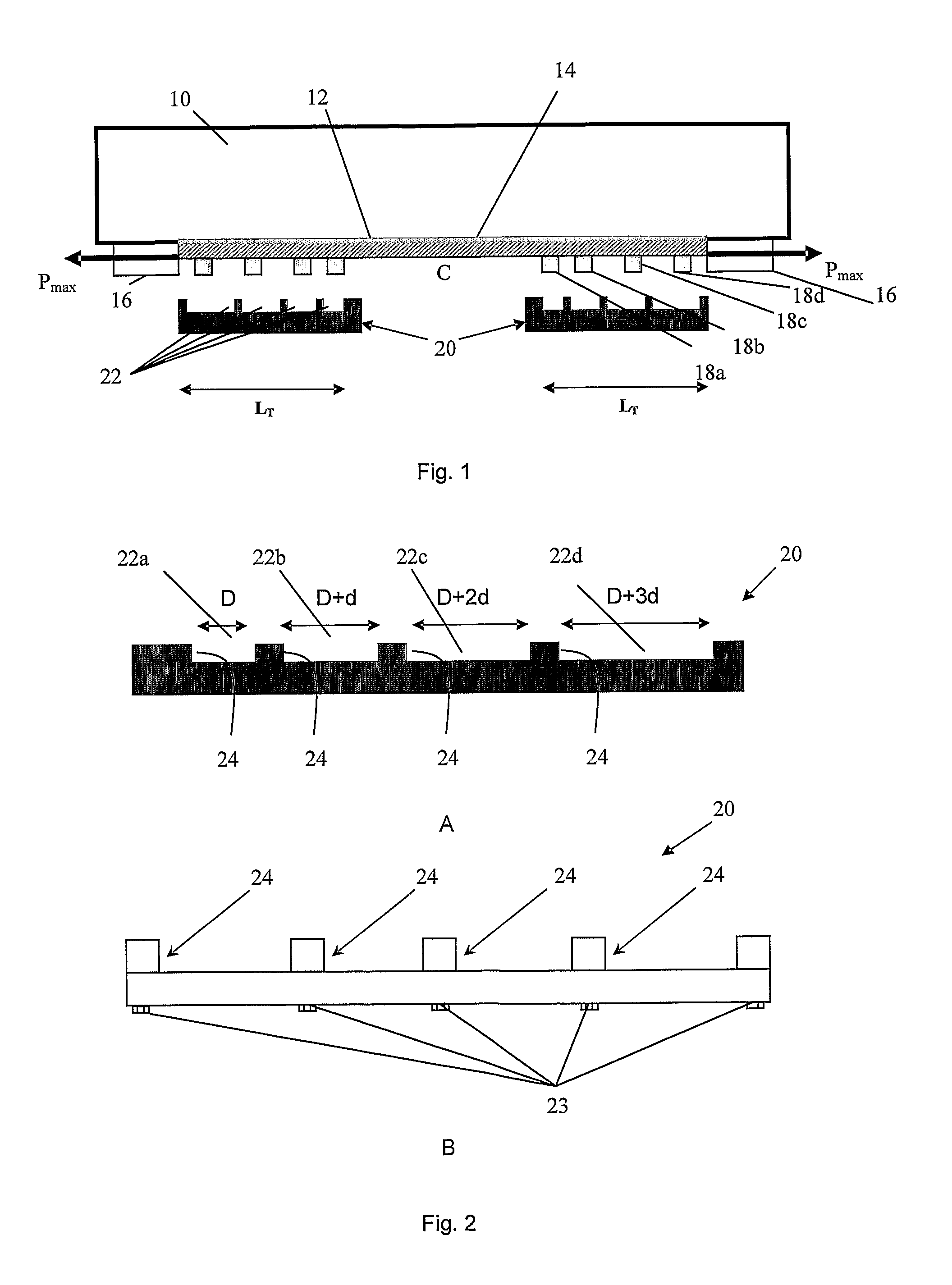
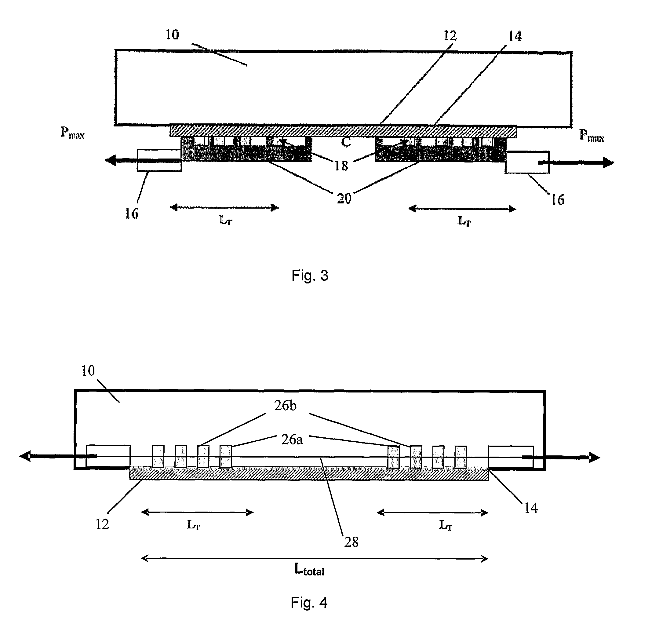
[0043]FIG. 1 shows a structural member 10, in the form of a beam constituting part of the span of a bridge for example. An FRP laminate 12 in the form of a lamellar strip, such as a pre-cured CFRP laminate, has been applied to the structural member by coating a surface of the structural member 10 with a continuous or discontinuous layer of curable adhesive 14 and pressing the FRP laminate 12 against the adhesive-coated surface. The FRP laminate 12 is applied to the bottom surface of the structural member 10 so that its fibres are parallel to the structural member's longitudinal axis.

[0044]A pre-stressing force, Pmax is then applied to each end of the FRP laminate 12 using a pre-stressing device 16 comprising two lockable units located in the vicinity of the ends of the FRP laminate 12 and attached to the structural member 10 for example. The exact degree of pre-stressing may be measured with strain gauges positioned on the FRP laminate 12, or by means of an integral force measuring ...


PUM

PropertyMeasurementUnit
shear stressesaaaaaaaaaa
lengthaaaaaaaaaa

Abstract

Method for applying a reinforced composite material, such as a fibre reinforced polymer (FRP) laminate or a steel reinforced polymer (SRP) laminate or a steel reinforced grout (SRG) composite, to a structural member. The method comprises the steps of: applying a curable adhesive to a surface of the structural member and / or a surface of the reinforced composite material, and bringing said surfaces into contact. A pre-stressing force, Pmax, is directly or indirectly applied to the reinforced composite material. The pre-stressing force, Pmax, to which a treatment length, LT, of the reinforced composite material is subjected is then decreased so that the reinforced composite material along the treatment length, LT, will be less pre-stressed than the reinforced composite material adjacent to the treatment length, LT, when the adhesive has cured.

Description

TECHNICAL FIELD[0001]The present invention concerns a method for applying a reinforced composite material, such as a fibre reinforced polymer (FRP) laminate or a steel reinforced polymer (SRP) laminate or a steel reinforced grout (SRG) composite, to a structural member, such as a part of a bridge, building, vehicle or any other structural member that needs to be strengthened or repaired.BACKGROUND OF THE INVENTION[0002]A fibre-reinforced polymer (FRP) is a composite material comprising a polymer matrix reinforced with fibres. The fibers are usually glass, carbon, aramid or metallic fibres, such as steel fibres, while the matrix is usually an epoxy, vinylester, nylon or polyester thermosetting plastic. FRPs are typically organized in a laminate structure, such that each lamina contains an arrangement of unidirectional fibres or woven fibre fabrics embedded within a thin layer of light polymer matrix material. The fibres provide the strength and stiffness. The matrix binds and protect...

Claims


Application Information

Patent Timeline
Patent Type & Authority Patents(United States)
IPC IPC(8): B32B37/00
CPCE04C5/085E04G23/0218Y10T156/10E04G2023/0251E04G2023/0255
Inventor AL-EMRANI, MOHAMMADKLIGER, ROBERTHAGHANI, REZA
Owner AL EMRANI MOHAMMAD
Why Eureka
Try Eureka