Illuminated tiling system

a technology of illumination and tiling, which is applied in the direction of lighting and heating apparatus, coupling device connection, lighting support device, etc., can solve problems such as components on the wall, and achieve the effect of simple and cost-effectiv

Inactive Publication Date: 2013-01-22
SIGNIFY HLDG BV
View PDF25 Cites 6 Cited by
  • Summary
  • Abstract
  • Description
  • Claims
  • Application Information

AI Technical Summary

Benefits of technology

[0003]Based on this background it was an object of the present invention to provide an illuminated tiling system that is simple and cost-effective with respect to its production and / or installation.
[0010]The described illuminated tiling system provides a very flexible and easy-to-use approach for integrating light-tiles into a conventional tiling of a wall, because the back panel with its conductive layer(s) provides an electrical power supply within large areas of the wall, optionally over the whole wall. This power supply can be contacted at any desired location by simply piercing the plug of the system into the back panel, wherein this piercing can be done after conventional tiling, i.e. when the exact place for the desired light-tile is known. Said light-tile can then be connected to the plug, thus providing the desired illumination within the tiling.
[0014]The electrical coupling between the plug-terminal and the tile-terminal, which allows the transfer of electrical energy and / or signals from the conductive layer(s) of the back panel to the light source, may for example be achieved by a direct electrical (physical) contact between these terminals. Alternatively, the terminals may be wirelessly coupled. In the latter case, the terminals are designed as (small) antennas or coils that emit and receive energy via electromagnetic waves. A wireless coupling has the advantage that the terminals can completely be embedded into an isolation that protects them from corrosion.
[0015]The main task of the plug is to provide the plug terminal(s) via which the light-tile can be coupled to the conductive layer(s) in the back panel. Optionally the plug and the light-tile may further comprise cooperating connection units for also mechanically coupling them. The connection units may for example be of a plug-socket type, with the male unit located on the light-tile and the female unit on the plug or vice versa. Mechanically attaching the light-tile to the plug makes the fixation of the light-tiles independent of the glue or mortar used for fixation of the conventional tiles. Moreover, such a connection is typically reversible, i.e. the light-tile can readily be exchanged if necessary.
[0026]To accomplish the tiling process of the wall, it is required that at least one plug of the illuminated tiling system is pierced into the back panel such that it electrically contacts the at least one conductive layer of the back panel. This piercing may be done before the dummy-tile is attached to the back panel (step c) or after it has been removed from the back panel (step d). The first variant has the advantage that mortar or glue which may be present on the back panel where the plug shall be inserted is still soft.

Problems solved by technology

A problem of this approach is that the components on the wall have to be precisely located in advance.

Method used


Image

  • Illuminated tiling system
  • Illuminated tiling system
  • Illuminated tiling system

Examples


Embodiment Construction

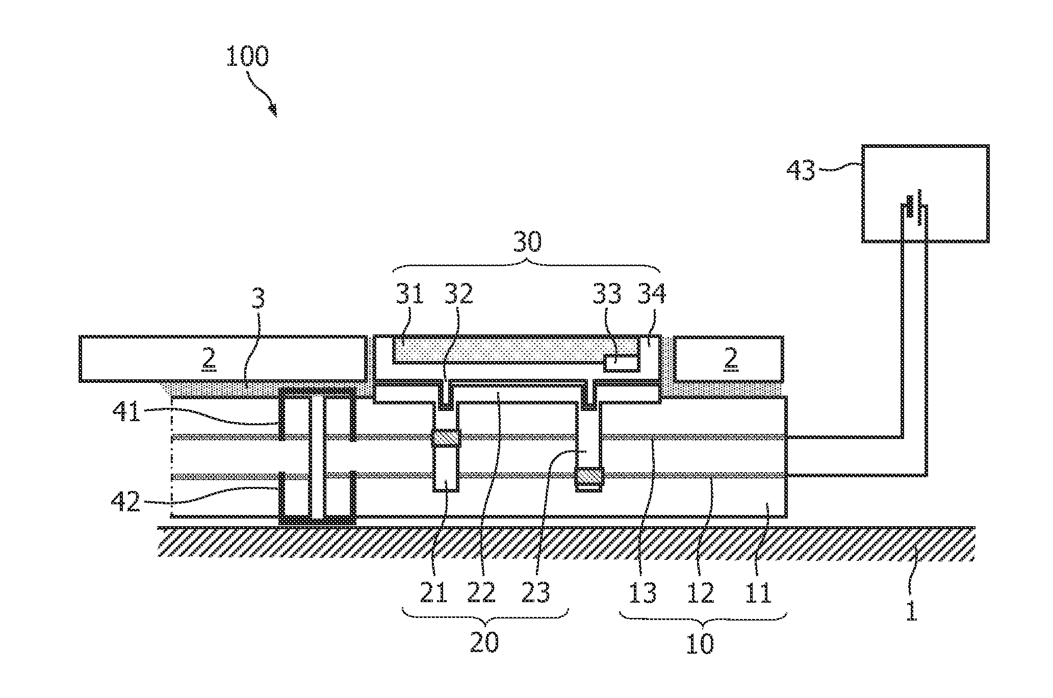
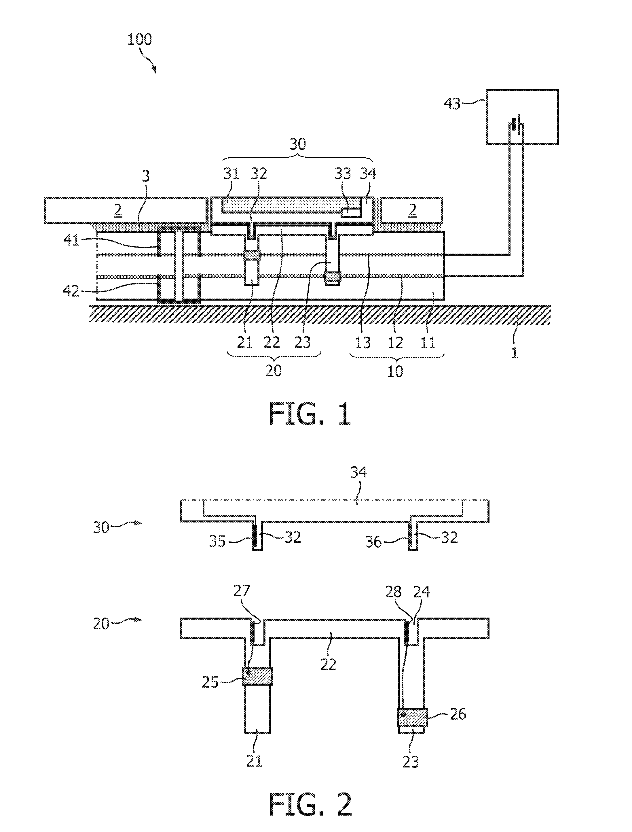
[0032]Like reference numbers in the Figures refer to identical or similar components.

[0033]Tiles and mosaics as they are for example found in bathrooms provide nice opportunities for incorporating a lighting, wherein a “mosaic” is by definition a regular or irregular pattern of (typically small) flagstones. As light sources, LEDs can be used in this case. To avoid a point source characteristic, it is further preferred to use OLEDs as light sources, which offer the following advantages:[0034]homogeneous light;[0035]extreme small thickness;[0036]large area;[0037]easy dimmable;[0038]cold surface;[0039]color variability;[0040]different forms (e.g. letters, symbols);[0041]variable off-state appearance.

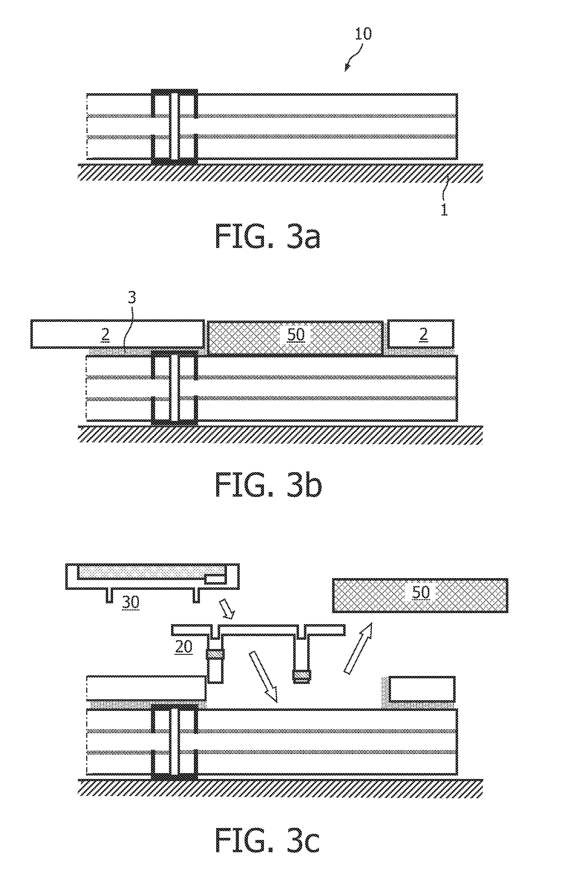
[0042]When trying to incorporate light sources into a tiling or mosaic, the following problems have to be faced:[0043]Pre-installation of the light sources is practically impossible, because the exact position has to be known as the alignment of the tiles is very critical.[0044]Additionally...


PUM


Abstract

The invention relates to an illuminated tiling system (100) which comprises back panels (10) with at least one electrically conductive layer (12, 13), plugs (20) with projections (21, 23) that electrically contact the conductive layer(s) (12, 13), and light-tiles (30) with (O)LEDs that can be fixed to the plugs. For an easy tiling, dummy-tiles can first be tiled together with conventional tiles (2) and later be replaced with the light-tiles (30).

Description

FIELD OF THE INVENTION[0001]The invention relates to an illuminated tiling system, a dummy-tile for such a system, and a method for tiling a wall using such an illuminated tiling system.BACKGROUND OF THE INVENTION[0002]The WO 2007 / 112851 A1 discloses illuminated tiles comprising an organic light emitting diode (OLED) in a housing. Snap-in elements at the back of the housing cooperate with corresponding snap-in elements preinstalled on the wall to connect the OLED to an electrical power supply. A problem of this approach is that the components on the wall have to be precisely located in advance.SUMMARY OF THE INVENTION[0003]Based on this background it was an object of the present invention to provide an illuminated tiling system that is simple and cost-effective with respect to its production and / or installation.[0004]This object is achieved by an illuminated tiling system according to claim 1, a dummy-tile according to claim 8, and a method according to claim 9. Preferred embodiment...

Claims


Application Information

Patent Timeline
Patent Type & Authority Patents(United States)
IPC IPC(8): F21S8/00
CPCE04F13/08E04F15/02E04F15/02144E04F15/18E04F21/0092F21V21/002F21V23/06F21V33/006E04F2290/026F21Y2101/02F21Y2105/008H01R4/2404H01R25/145E04F15/02133F21Y2105/00F21Y2115/15E04F13/074
Inventor VERJANS, CONRAD WILHELMUS ADRIAANSAUERLAENDER, GEORGJACOBS, JOSEPH HENDRIK ANNA MARIAHENTE, DIRK
Owner SIGNIFY HLDG BV
Why Eureka
Try Eureka