Rear-mounted aerodynamic structure for truck cargo bodies

an aerodynamic structure and cargo technology, applied in the direction of roofs, transportation and packaging, vehicle arrangements, etc., can solve the problems of reducing the open framework reduces the chance of accretion of debris and snow, so as to facilitate the folding of all panels

Inactive Publication Date: 2013-01-29
STEMCO PROD INC
View PDF53 Cites 61 Cited by
  • Summary
  • Abstract
  • Description
  • Claims
  • Application Information

AI Technical Summary

Benefits of technology

[0011]This invention overcomes disadvantages of the prior art by providing foldable / retractable and unfoldable / deployable, rearwardly tapered aerodynamic assembly for use on the rear trailer bodies and other vehicles that accommodate dual swing-out doors. The aerodynamic assembly includes a right half mounted on the right hand door and a left half mounted on a left hand door. Each half is constructed with a side panel, top panel and bottom panel, which form half of an overall tapered box when deployed on the rear of the vehicle, the bottom panels and top panels being sealed together at a pair of overlapping weather seals along the centerline. The panels are relatively thin, but durable, and are joined to each other by resilient strip hinges. The top and bottom panels are also hinged to form two sections along diagonal lines to facilitate folding of all panels in a relatively low-profile stacked orientation. This low profile allows the doors to be swung through approximately 270 degrees to be secured to the sides of the body in a manner that does not interfere with adjacent doors or bodies in, for example a multi-bay loading dock. A swing arm assembly and gas spring biases the panels into a deployed position that can be refolded by grasping the side panel and rotating it inward toward the door surface. The top and bottom panels are partly inwardly folded when deployed to define external valleys using a stop assembly. This ensures that the panels fold readily when desired without the two sections of the panels “locking up” due to an overly planar profile.
[0012]While the panels herein include weather seals to enhance aerodynamic efficiency, it is contemplated, in alternate embodiments that panels can confront each other with small gaps, free of an engaging seals. Alternatively the seals can be lightly engaging or provide small gaps therebetween that may become more closely engaging at high speeds (under increased airflow).
[0014]In an illustrative embodiment, a spring assembly is operatively connected at a first end to at least one of the right hand door and the left hand door, and is constructed and arranged to respectively bias at least one of the right aerodynamic assembly half and the left aerodynamic assembly half into the unfolded orientation. This spring can include a damper and can illustratively comprise a gas spring that is mounted between a bracket on each door and a vertical member at the far end of each swing arm. In this manner the swing arm provides a coordinated bias force to the top and bottom panels, which, in turn bias the interconnected side panel into the unfolded orientation. Moreover, the top and bottom panels can be mounted on hinges to their respective door using hinges that define an angled hinge axis. In this manner the door-facing edges of top and bottom panels remain horizontal across the width when deployed, but define a gap that tapers inwardly when folded so as to provide clearance for the door lock rods and other components, such as the swing arm assemblies. In an embodiment, the panels are hinged together using strips of a resilient material that is fastened at each side of the junction to the associated panel. These hinges allow for breakage in the event of an impact, and also allow for modest misalignment when folded, thereby facilitating the stacking of the panels when folded. The side panels can include a latch component, such as a pin along their rear interior face. This selectively engages a second latch component on the exterior face of the bottom panel, near the door and centerline. In general, the bottom panels can be located at a position on the door above door lock rod handles for ease of access to the locking system when the panels are folded. Moreover, the bottom panels can be formed as an open framework, with hinge positions and other connection bases provided within the framework, similarly to those in a solid panel. An open framework reduces the chances of accretion of debris and snow in certain climates. The panels can also be mounted on dual-swinging doors or frameworks that selectively latch to the vehicle rear, and that swing outwardly to reveal an inner door of a non-dual-swinging, such as a roll up doors. The overlying doors or frameworks operate to swing approximately 270 degrees in the same manner as regular dual-swinging doors.

Problems solved by technology

An open framework reduces the chances of accretion of debris and snow in certain climates.

Method used


Image

  • Rear-mounted aerodynamic structure for truck cargo bodies
  • Rear-mounted aerodynamic structure for truck cargo bodies
  • Rear-mounted aerodynamic structure for truck cargo bodies

Examples


Embodiment Construction

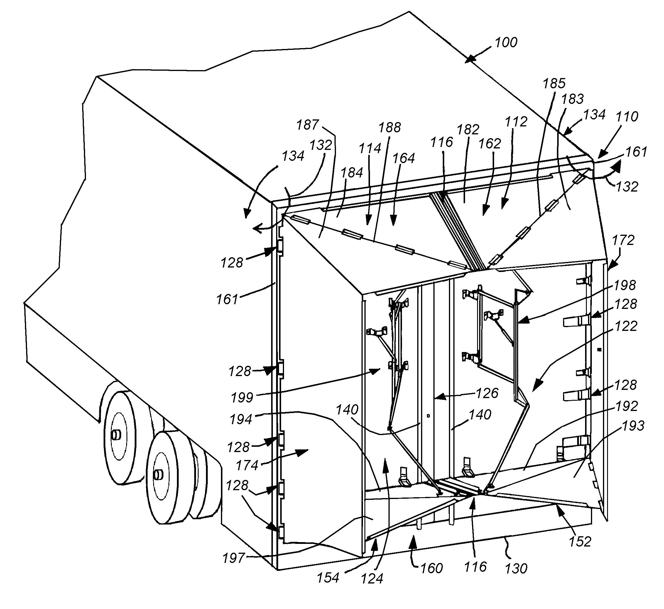
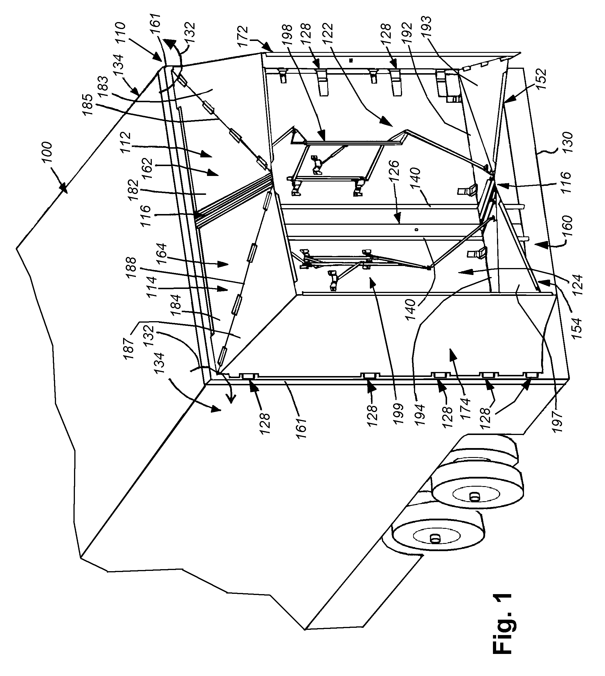
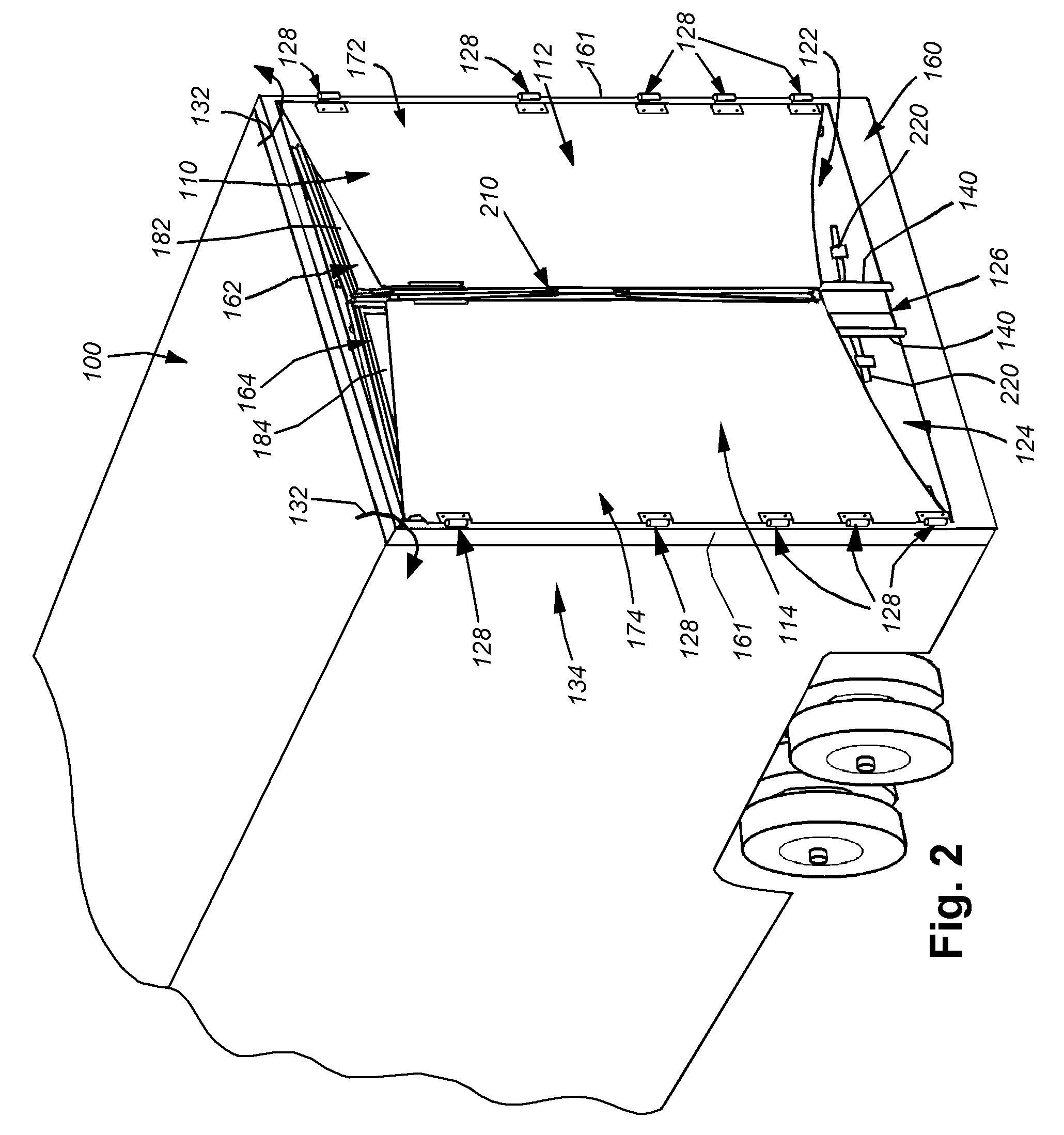
[0033]FIG. 1 details the rear end of a conventional tractor trailer body 100, which has been provided with aerodynamic assembly 110 along its rear end. The assembly operates to reduce drag as a truck and trailer move at high speed down a roadway. For background, the operation of an aerodynamic assembly having a panel arrangement similar to that shown herein is described in the above-incorporated U.S. patent application Ser. No. 12 / 122,645, published as U.S. Published Application No. 2008 / 0309122 A1, filed May 16, 2008, entitled REAR-MOUNTED AERODYNAMIC STRUCTURE FOR TRUCK CARGO BODIES, the teachings of which are expressly incorporated herein by reference as further background information. The aerodynamic assembly 100 is arranged in two halves. A right half 112 is mounted with respect to a right-hinged door 122, and a left half 114 is mounted with respect to a left-hinged door 124. A joint 116 between the halves 112 and 114 is provided. This joint is aligned with the joint 126 betwee...


PUM


Abstract

This invention provides a foldable / retractable and unfoldable / deployable, rearwardly tapered aerodynamic assembly for use on the rear trailer bodies and other vehicles that accommodate dual swing-out doors. The aerodynamic assembly includes a right half mounted on the right hand door and a left half mounted on a left hand door. Each half is constructed with a side panel, top panel and bottom panel, which each form half of an overall tapered box when deployed on the rear of the vehicle, the bottom panels and top panels being sealed together at a pair of overlapping weather seals along the centerline.

Description

RELATED APPLICATIONS[0001]This application is a continuation-in-part of U.S. patent application Ser. No. 12 / 122,645, filed May 16, 2008, now U.S. Pat. No. 8,100,461, entitled REAR-MOUNTED AERODYNAMIC STRUCTURE FOR TRUCK CARGO BODIES, the entire disclosure of which is herein incorporated by reference, which claims the benefit of copending U.S. Provisional Application Ser. No. 61 / 039,411, filed Mar. 25, 2008, entitled REAR-MOUNTED AERODYNAMIC STRUCTURE FOR TRUCK CARGO BODIES, the entire disclosure of which is also herein incorporated by reference, and which also claims the benefit of copending U.S. Provisional Application Ser. No. 60 / 938,697, filed May 17, 2007, entitled REAR-MOUNTED AERODYNAMIC STRUCTURE FOR TRUCK CARGO BODIES, the entire disclosure of which is also herein incorporated by reference.FIELD OF THE INVENTION[0002]This invention relates to aerodynamic structures mounted on the rear end of truck bodies, and more particularly to deployable and retractable aerodynamic struct...

Claims


Application Information

Patent Timeline
Patent Type & Authority Patents(United States)
IPC IPC(8): B62D35/00
CPCB62D35/001B62D63/08B62D35/004B62D35/00B62D37/02B62D35/007
Inventor SMITH, ANDREW F.HORRELL, CHARLES M.GROSSMANN, JEFFREY J.
Owner STEMCO PROD INC
Why Eureka
Try Eureka