Magnetic mask holder

a magnetic mask and holder technology, applied in the field of magnetic mask holders, can solve the problems of unfavorable arrangement, unoptimized rapid and precise handling of mask changes, etc., and achieve the effects of simple operation, rapid and simple possibility of mask changes, and convenient manufactur

Inactive Publication Date: 2013-01-29
APPLIED MATERIALS GMBH & CO KG
View PDF34 Cites 10 Cited by
  • Summary
  • Abstract
  • Description
  • Claims
  • Application Information

AI Technical Summary

Benefits of technology

[0008]At least one aspect of the invention is directed to a mask holder for dynamic vacuum-coating processes, especially during the in-line production of OLED screens or displays, that avoids the disadvantages of the prior art and especially guarantees a precise, rapid and simple possibility of mask changing, and a secure and reliable arrangement of the mask at the (dynamic) substrate moved during coating. Especially, the corresponding devices for mask changing are to be easy to manufacture and simple to operate.
[0010]By means of this arrangement, the substrate is treated carefully for one thing since the holding function for the mask transfers directly to the substrate carrier. For another, on account of the magnetic holder, simple handling and secure holding of the mask during transport through the vacuum-coating machine are assured. By virtue of the predetermined arrangement of the magnets on the substrate carrier and of the use of several localized magnets opposite large-surface magnets, simple interaction with a corresponding handling device, which may preferably feature switchable electromagnets, is assured.
[0014]When a frame is used, it is additionally possible to clamp the thin foil-like masks along the foil plane as well such that they feature greater stability perpendicular to the foil plane.
[0015]Further, the use of a frame or the arrangement of the holding magnets relative to the edge of the mask facilitates stable attachment of them by correspondingly high magnetic forces.
[0018]Additionally, even more magnets may be provided in or at the substrate carrier in the actual mask area in order that, especially in the case of magnetic masks, full-surface pressing of the mask against the substrate may be assured.

Problems solved by technology

In such an arrangement for a mask holder, the mechanical attachment of the mask to the substrate carrier promotes the generation of undesirable particles and, moreover, such an arrangement is unfavourable for simple, quick and precise arrangement and removal of the mask from the substrate.
Although such magnetic attraction of the mask against the substrate enables full contact to be obtained between the mask and the substrate and hence freedom from blisters, and sharp coating edges, such an arrangement is not optimal for rapid, precise handling with regard to mask changing, especially under vacuum conditions.

Method used


Image

  • Magnetic mask holder
  • Magnetic mask holder
  • Magnetic mask holder

Examples


Embodiment Construction

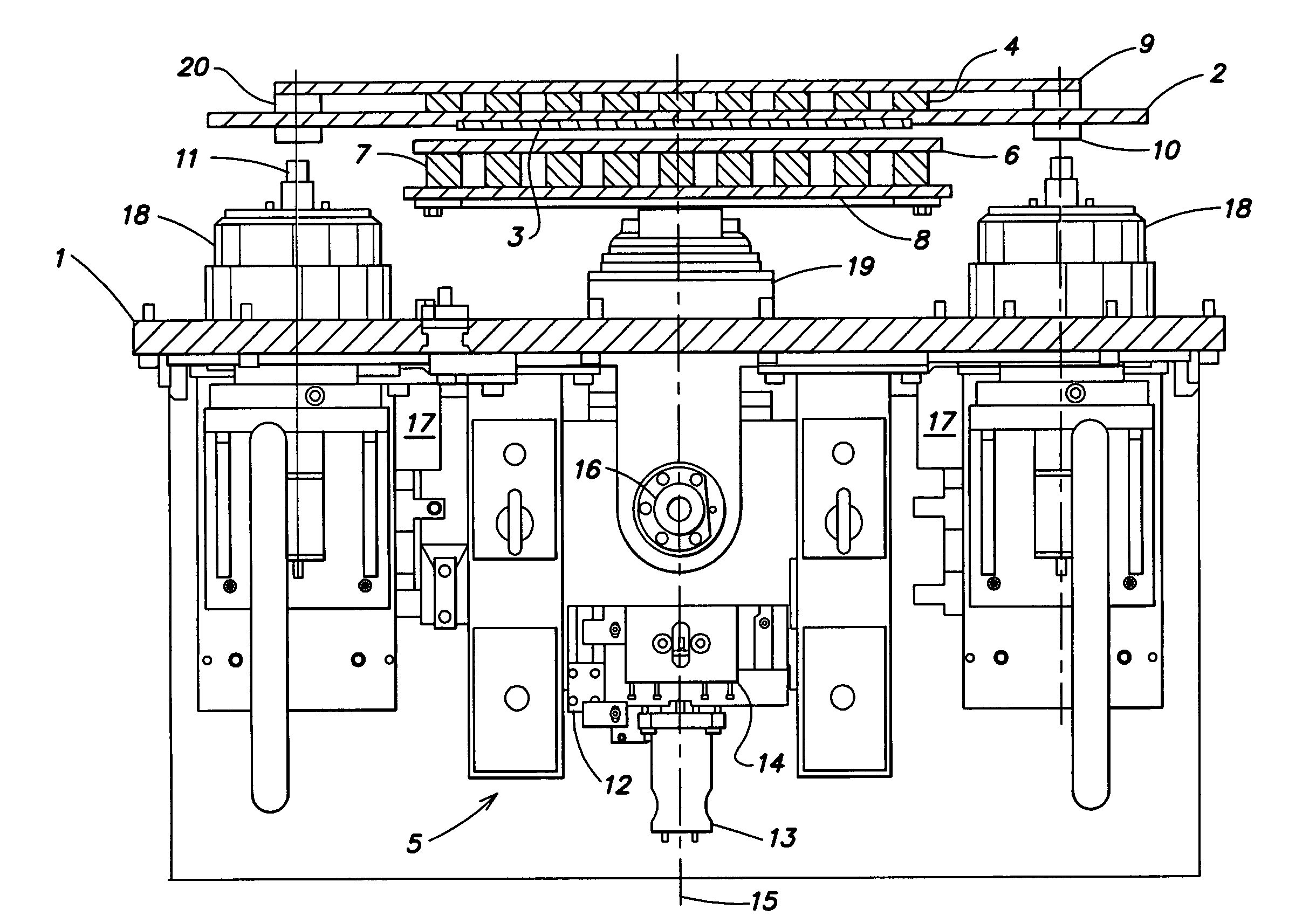
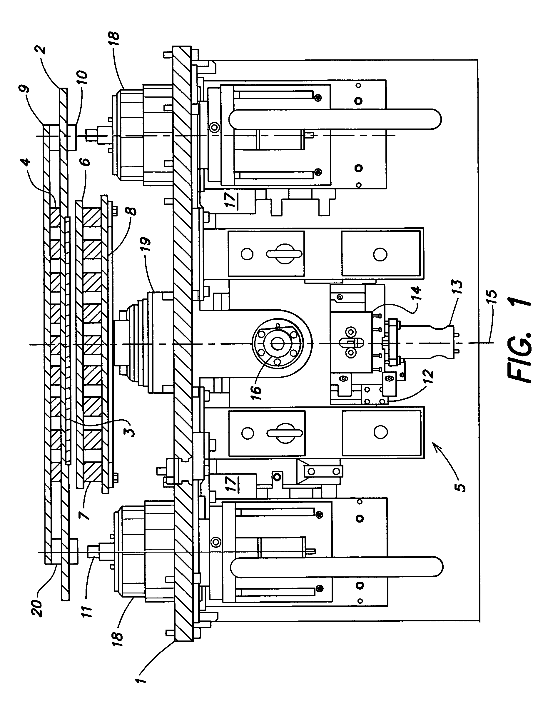
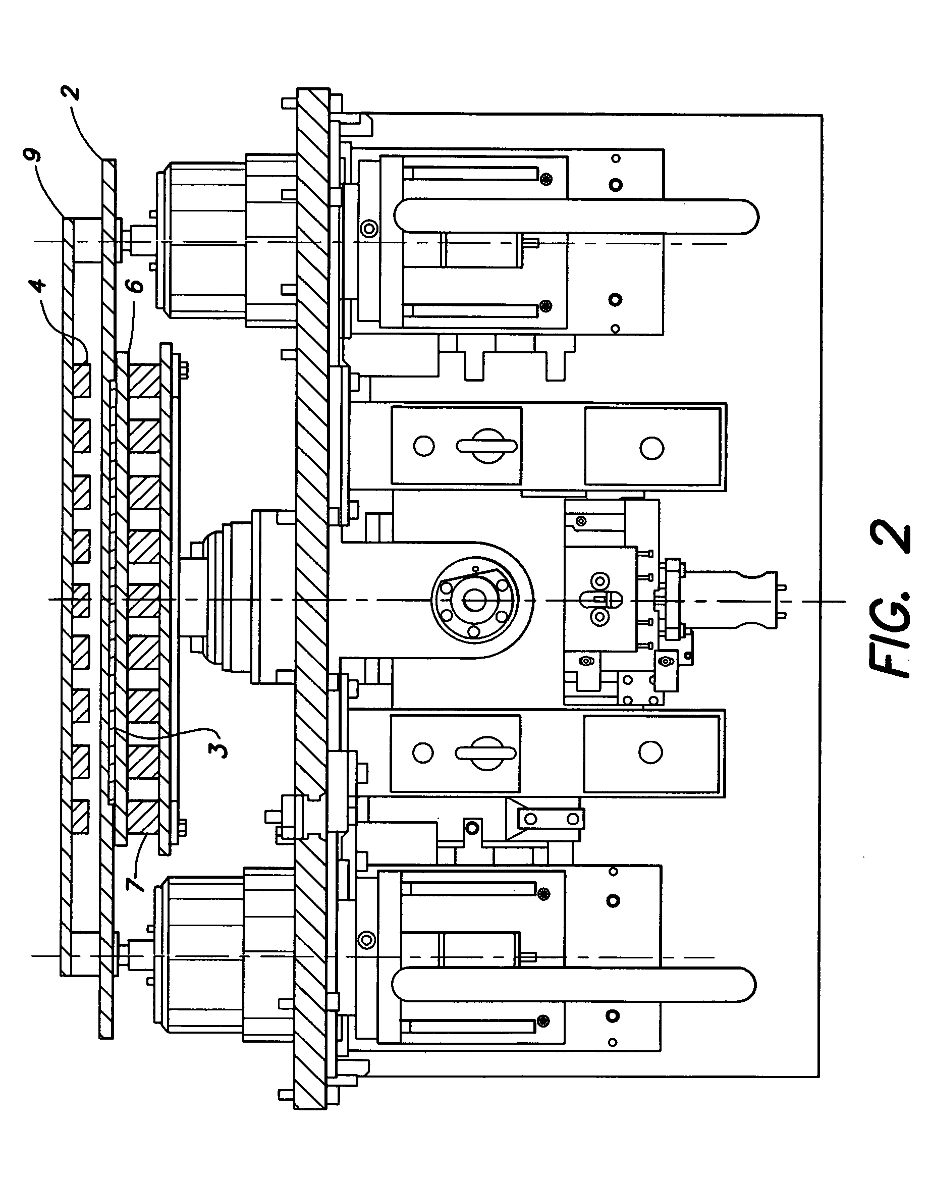
[0024]FIG. 1 is a lateral view and partial cross-sectional view of a mask-application station for a vacuum chamber of a vacuum-coating machine, especially for the continuous (in-line) coating of transparent substrates with organic, electroluminescent materials for the production of OLED displays or screens.

[0025]FIG. 1 shows a cross-section through a chamber wall or a mounting plate 1, which can be inserted into the chamber wall, whereby, in the vacuum chamber, i.e. above the mounting plate 1 of FIG. 1, a substrate carrier 2 is shown with a substrate 3 arranged on it, which can be transported through the vacuum chamber by means of transport or conveyor devices not shown.

[0026]In the state shown in FIG. 1, the substrate is located above a mask-application station with mask-positioning device 5, with the aid of which mask 6 can be arranged and aligned on substrate 3.

[0027]The mask-positioning device 5 features a large number of electromagnets 7, which are arranged peripherally around ...


PUM

PropertyMeasurementUnit
areaaaaaaaaaaa
perimeteraaaaaaaaaa
electroluminescentaaaaaaaaaa

Abstract

Aspects of the present invention are directed to a mask holder for especially large-surface substrates, especially for the micro-structuring of organic electroluminescent materials (OLED) for the production of OLED screens, displays and the like by means of vacuum-coating processes, with a substrate carrier for receiving the substrate during coating processes, with the substrate carrier comprising one or more magnets and the mask features a frame of magnetic material, such that the frame of the mask is held by means of the magnets of the substrate carrier relative to the substrate to be coated.

Description

RELATED APPLICATION[0001]This application relates to U.S. patent application Ser. No. 11 / 407,343 entitled PROCESS AND DEVICE FOR POSITIONING THE MASK, by Dieter Manz, filed on even date herewith, and U.S. patent application Ser. No. 11 / 406,806 entitled CONTINUOUS OLED COATING MACHINE, by Dieter Manz, Marcus Bender, Uwe Hoffmann, Dieter Haas, Ulrich Englert, Heino Lehr and Achim Gttrke, filed on even date herewith. Both of these related applications are incorporated herein by reference.BACKGROUND OF INVENTION[0002]The present invention relates to a mask holder for especially large-surface substrates, especially for the microstructuring of organic electroluminescent materials (OLED) on preferably large-surface substrates, especially screens, displays and the like by means of vacuum-coating processes.[0003]In the production of so-called OLED displays or screens, which utilize the light-emitting properties of organic, electroluminescent materials (OLED), it is necessary to apply organic...

Claims


Application Information

Patent Timeline
Patent Type & Authority Patents(United States)
IPC IPC(8): C23C16/00C23F1/00H01L21/306B05C11/11
CPCC23C14/042H05B33/10
Inventor MANZ, DIETER
Owner APPLIED MATERIALS GMBH & CO KG
Why Eureka
Try Eureka