Process and device for positioning the mask

Inactive Publication Date: 2007-01-11
APPLIED MATERIALS GMBH & CO KG
View PDF6 Cites 46 Cited by
  • Summary
  • Abstract
  • Description
  • Claims
  • Application Information

AI Technical Summary

Benefits of technology

[0008] At least one aspect of the invention is directed to a process and a device for mask changing, especially for arrangement and alignment in dynamic vacuum-coating processes for in-line production of OLED screens or displays, that avoid disadvantages of the prior art and espec

Problems solved by technology

In such an arrangement for a mask holder, the mechanical attachment of the mask to the substrate carrier promotes the generation of undesirable particles and, moreover, such an arrangement is unfavourable for simple, quick and precise arrangement and removal of the mask from the substrate.
Although such mag

Method used


Image

  • Process and device for positioning the mask
  • Process and device for positioning the mask
  • Process and device for positioning the mask

Examples


Embodiment Construction

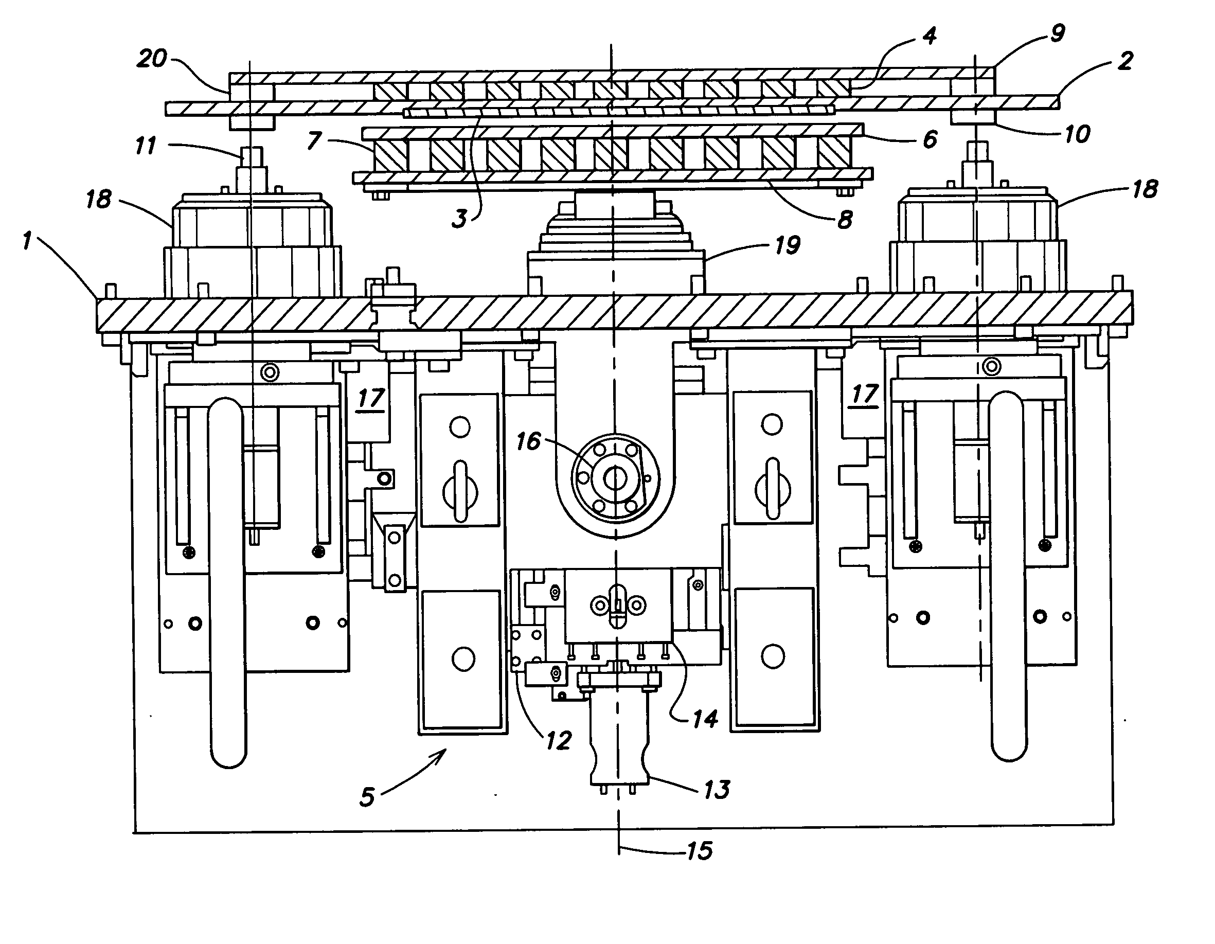
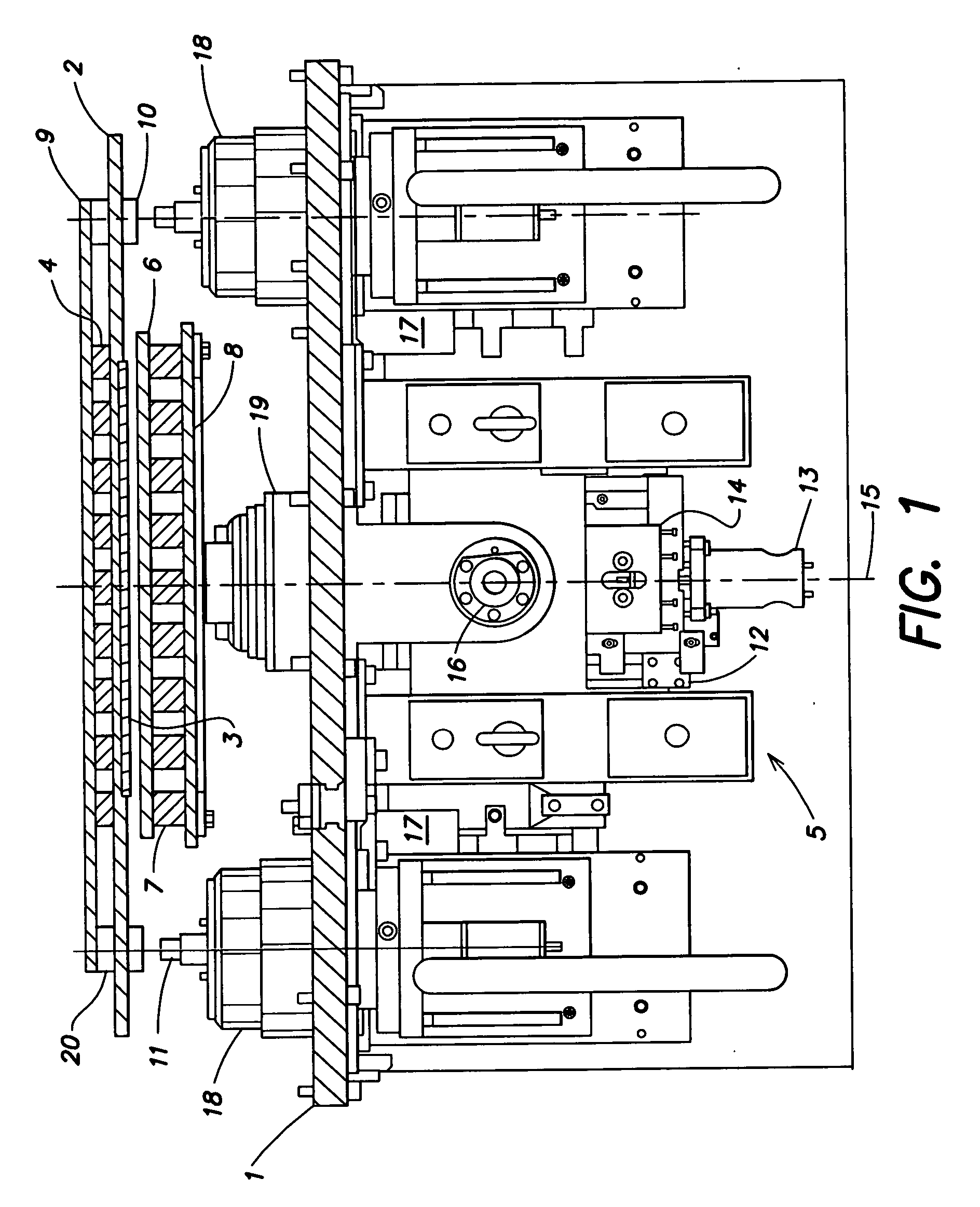
[0032]FIG. 1 is a lateral view and partial cross-sectional view of a mask-application station for a vacuum chamber of a vacuum-coating machine, especially for the continuous (in-line) coating of transparent substrates with organic, electroluminescent materials for the production of OLED displays or screens.

[0033]FIG. 1 shows a cross-section through a chamber wall or a mounting plate 1, which can be inserted into the chamber wall, whereby, in the vacuum chamber, i.e. above the mounting plate I of FIG. 1, a substrate carrier 2 is shown with a substrate 3 arranged on it, which can be transported through the vacuum chamber by means of transport or conveyor devices not shown.

[0034] In the state shown in FIG. 1, the substrate is located above a mask-application station with mask-positioning device 5, with the aid of which mask 6 can be arranged and aligned on substrate 3.

[0035] The mask-positioning device 5 features a large number of electromagnets 7, which are arranged peripherally ar...


PUM

PropertyMeasurementUnit
Electroluminescenceaaaaaaaaaa
Vacuumaaaaaaaaaa
Magnetismaaaaaaaaaa

Abstract

Aspects of the invention are directed to a device and a method for arranging/removing and aligning masks on substrates to be coated, especially for the micro-structuring of organic, electroluminescent materials (OLED) on preferably large-surface substrates, especially screens, displays and the like. In one version a process includes providing a substrate on a substrate carrier, the substrate carrier having magnets arranged peripherally around a substrate receiver area, holding the mask using electromagnets on a holding assembly moveable in several dimensions by a first movement device, determining relative positions of the mask and substrate to each other, aligning the substrate and mask with each other by actuating the first movement device such that the mask is moved relative to the substrate, if a misorientation has been determined, depositing the mask on the substrate by moving at least one of the holding assembly and the substrate carrier, and deactivating the electromagnets and holding the mask on the substrate by the magnets of the substrate carrier.

Description

RELATED APPLICATION [0001] This application relates to U.S. patent application Ser. No. ______ entitled MAGNETIC MASK HOLDER (Attorney Docket No. A2022-700110), by Dieter Manz, filed on even date herewith, and U.S. patent application Ser. No. ______ entitled CONTINUOUS OLED COATING MACHINE (Attorney Docket No. A2022-700210), by Dieter Manz, Marcus Bender, Uwe Hoffmann, Dieter Haas, Ulrich Englert, Heino Lehr and Achim Garke, filed on even date herewith. Both of these related applications are incorporated herein by reference.BACKGROUND OF INVENTION [0002] The present invention relates to a process and a device for arranging / removing and aligning masks on substrates to be coated, especially for the micro-structuring of organic electroluminescent materials (OLED) on preferably large-surface substrates, especially screens, displays and the like in a vacuum. [0003] In the production of so-called OLED displays or screens, which utilize the light-emitting properties of organic, electrolumi...

Claims


Application Information

Patent Timeline
IPC IPC(8): B05D1/32
CPCC23C14/042H05B33/10
Inventor MANZ, DIETER
Owner APPLIED MATERIALS GMBH & CO KG
Why Eureka
Try Eureka