Moving body equipped with fuel cells

a technology of moving body and fuel cell, which is applied in the field of moving body equipped with fuel cells, can solve the problems of fuel cell malfunction, blockage of the outlet, further run, etc., and achieve the effect of accurate detection of the level, effective use and reduced vehicle center of gravity

Active Publication Date: 2013-01-29
TOYOTA JIDOSHA KK
View PDF20 Cites 4 Cited by
  • Summary
  • Abstract
  • Description
  • Claims
  • Application Information

AI Technical Summary

Benefits of technology

[0007]In the moving body according to this aspect of the invention, the exhaust piping has the multiple outlets formed to discharge the exhaust fluid from the fuel cells to the outside of the moving body. At least two outlets among the multiple outlets are located at the positions of mutually different heights. The arrangement of the multiple outlets at the different heights effectively lowers the potential of simultaneous blockage of the multiple outlets by the various obstructing objects mentioned above, compared with the arrangement of multiple outlets at an identical height. For example, even when one outlet located at a relatively low position, for example, at an underfloor position in a rear portion of the main body of the moving body, is blocked by the water, soil, sand, and other equivalent substances on the road surface during drive of the moving body on the water-covered road, this arrangement ensures continuous power generation by the fuel cells with discharging the exhaust fluid to the outside of the moving body via an unblocked outlet located at a relatively high position. In another example, even when one outlet located at the relatively high position is blocked by some obstructing object, such as a falling object from the sky or a flying object, during drive of the moving body on the ordinary road surface, this arrangement ensures continuous power generation by the fuel cells with discharging the exhaust fluid to the outside of the moving body via an unblocked outlet located at the relatively low position. This arrangement of the invention accordingly enables the moving body equipped with the fuel cells to be continuously driven even in the specific circumstance where any of the various obstructing objects as the cause of blockage of the outlet is present in the surroundings of the moving body.
[0018]In the moving body having any of the arrangements discussed above, it is preferable that the fuel cells are located in an underfloor area of the moving body. One typical example of the moving body is a vehicle. In this example, this arrangement ensures the effective use of the underfloor space of the vehicle. The installation of the fuel cells in the underfloor area of the vehicle lowers the center of gravity of the vehicle and improves the driving stability of the vehicle. The vehicle equipped with the fuel cells generally has a cooling device (radiator) for cooling down the flow of cooling water, which is circulated to cool down the fuel cells. The radiator is provided in a front portion of the vehicle to utilize the driving wind of the vehicle for cooling down the flow of cooling water. The arrangement of the fuel cells installed in the underfloor area of the vehicle desirably leaves a wider space surrounding the radiator, compared with the arrangement of the fuel cells installed near to the radiator. This arrangement effectively enhances the heat release rate of the radiator and improves the air cooling efficiency of the cooling water.

Problems solved by technology

In the prior art structure disclosed in Japanese Patent Laid-Open No. 2002-289237, however, during drive of the vehicle equipped with the fuel cells on the water-covered road, the outlet may be blocked by the water, soil, sand, and other equivalent substances present on the road surface.
Such blockage of the outlet may interfere with the smooth discharge of the exhaust gas and the produced water and stop power generation by the fuel cells to eventually prevent further run of the vehicle.
The water, soil, sand, and other equivalent substances flowed into the outlet may run through the piping to reach the inside of the fuel cells and cause malfunction of the fuel cells.
This problem is not characteristic of the vehicle equipped with fuel cells but is commonly found in various moving bodies equipped with fuel cells and configured to be driven on the road surface with electric power generated by the fuel cells as the driving power source.

Method used


Image

  • Moving body equipped with fuel cells
  • Moving body equipped with fuel cells
  • Moving body equipped with fuel cells

Examples


first embodiment

A. First Embodiment

A1. Configuration of Fuel Cell System Mounted on Vehicle

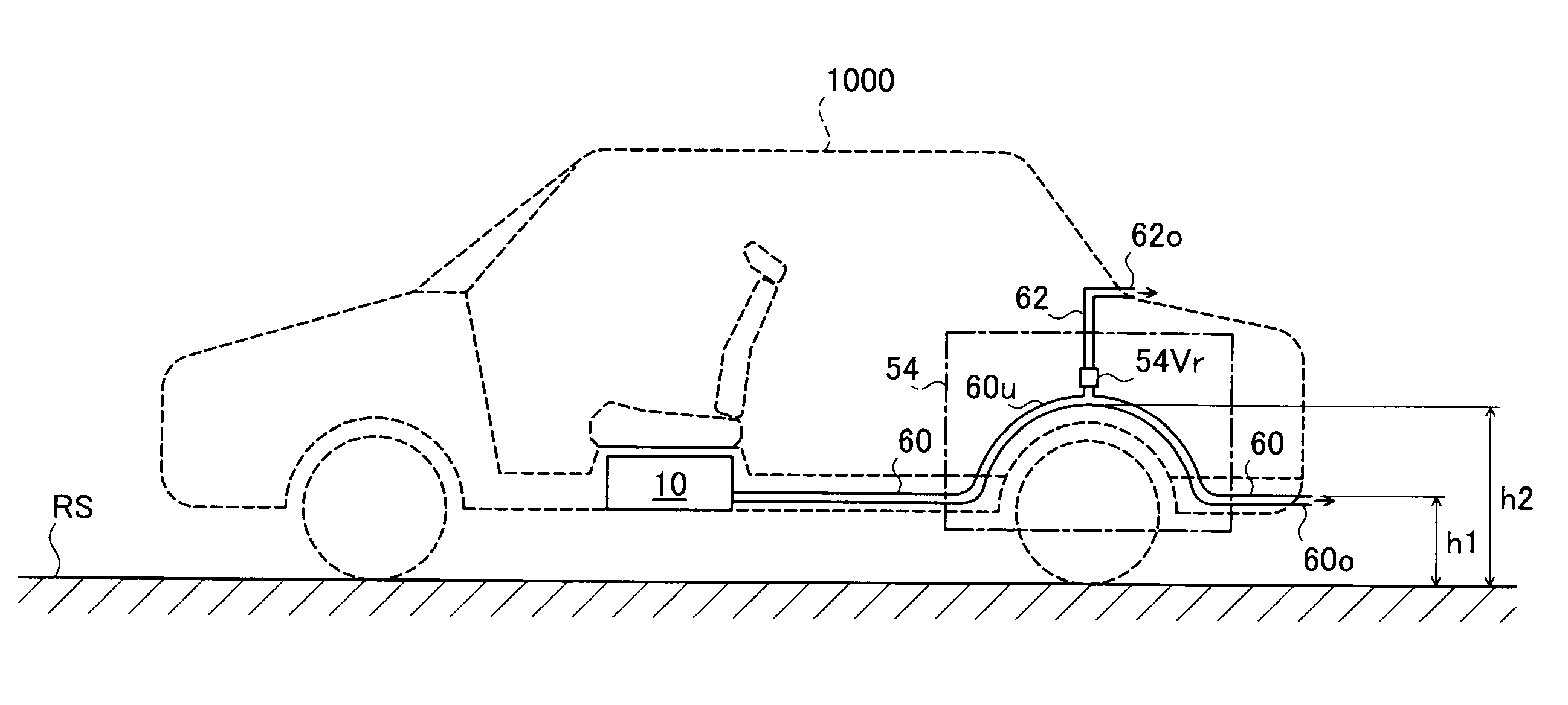
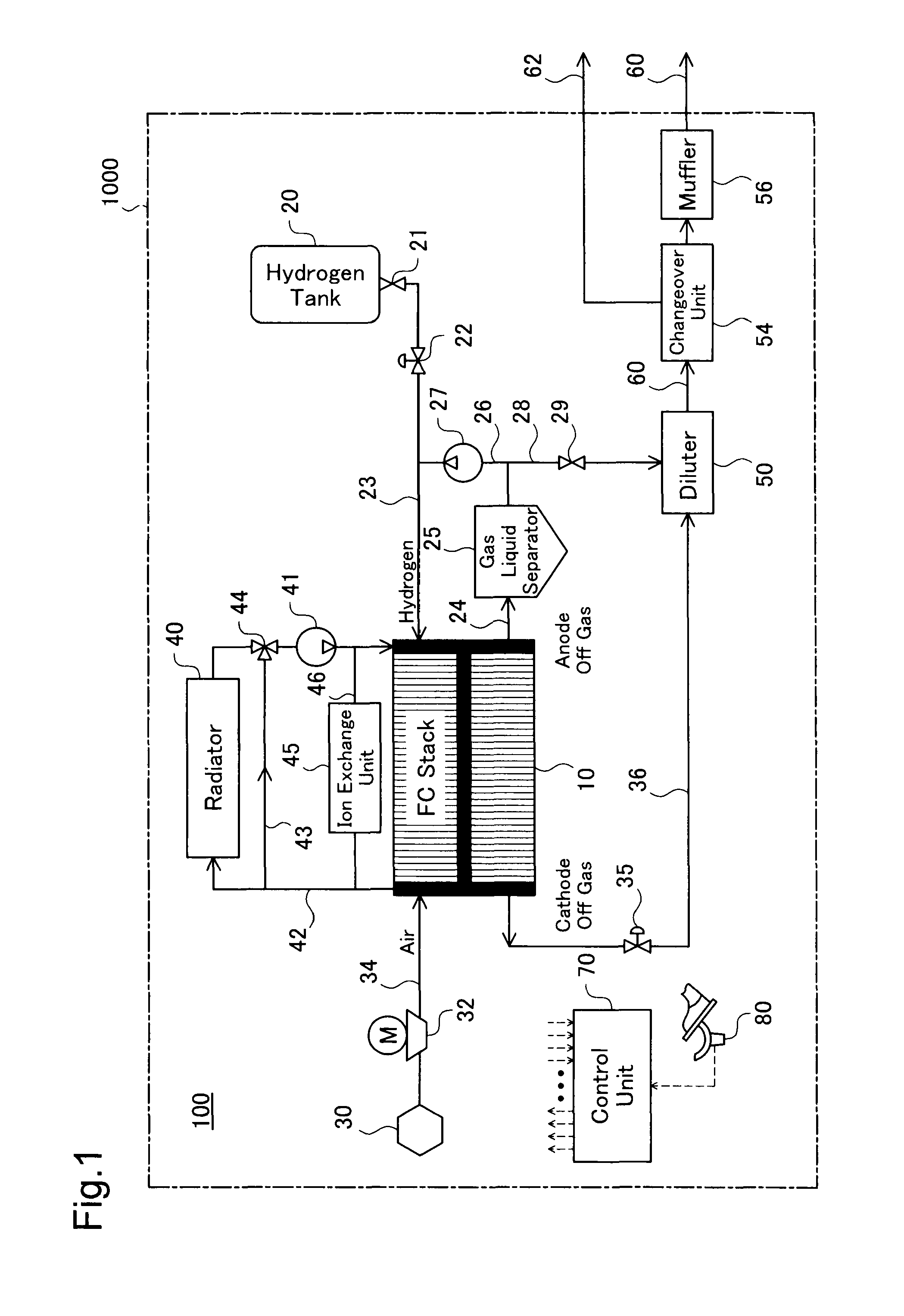
[0032]FIG. 1 schematically illustrates the configuration of a fuel cell system 100 mounted on a vehicle 1000 in one embodiment of the invention. The vehicle 1000 is an electric vehicle driven with rotation of an axle and wheels by the power of a motor, which is operated with electric power generated by the fuel cell system 100. In response to the driver's operation of an accelerator placed in the vehicle 1000, the fuel cell system 100 generates electric power according to the driver's accelerator operation amount detected by an accelerator opening sensor 80. The vehicle 1000 of the embodiment corresponds to the moving body of the invention.

[0033]A fuel cell (FC) stack 10 is constructed as a laminate of multiple cells designed to generate electric power through electrochemical reaction of hydrogen with oxygen. Each cell has a hydrogen electrode (hereafter referred to as anode) and an oxygen electrode (hereafte...

second embodiment

B. Second Embodiment

[0054]The vehicle 1000 of a second embodiment has the similar structure to that of the vehicle 1000 of the first embodiment, except the structure of a changeover unit in the fuel cell system 100. The structure of a changeover unit 54A of the second embodiment is described below.

B1. Structure of Changeover Unit

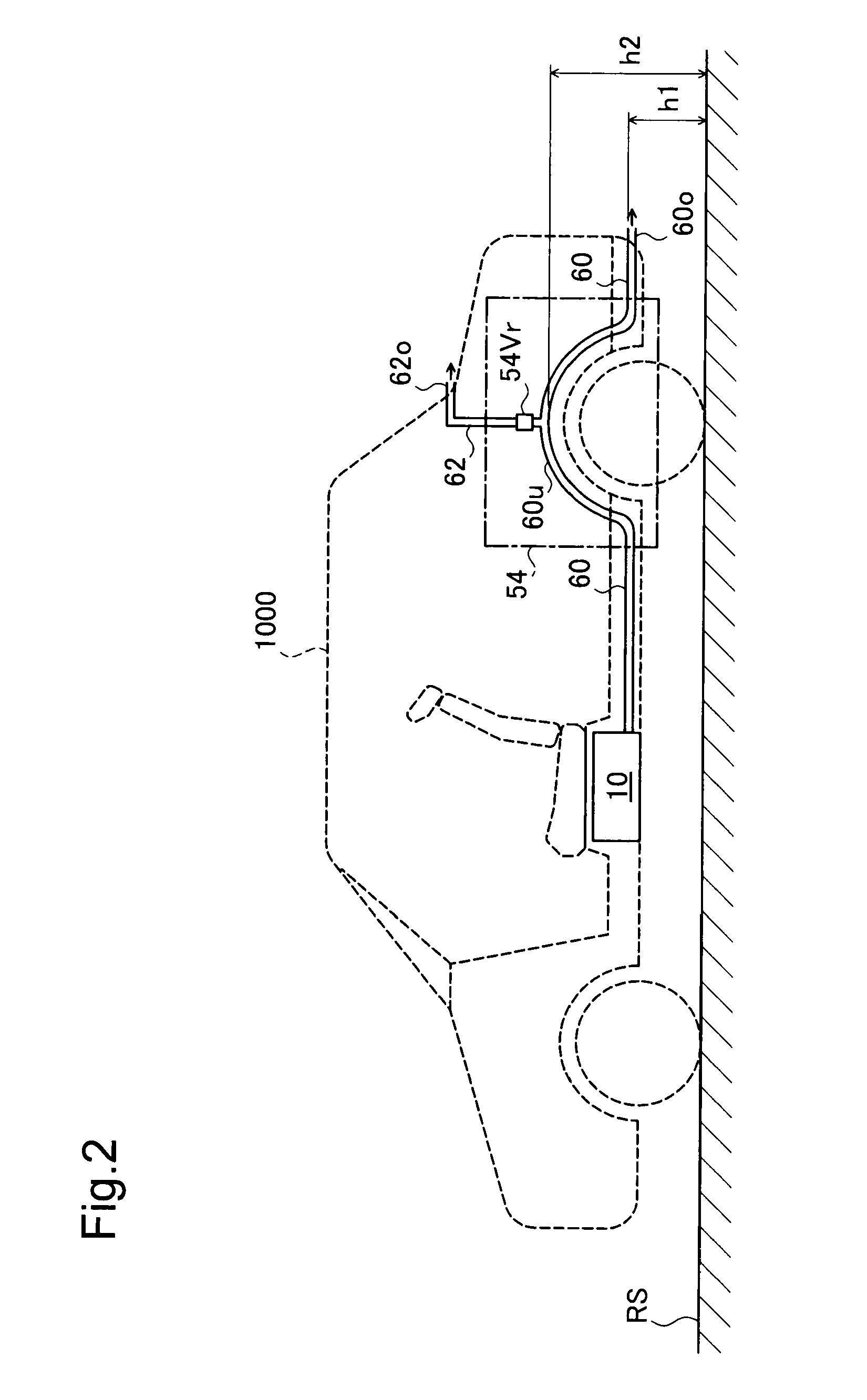
[0055]FIG. 3 shows the schematic structure of the changeover unit 54A of the second embodiment. As illustrated, like the structure of the first embodiment discussed previously, in the changeover unit 54A of the second embodiment, piping 60 includes a U tube 60u convex upward in a vertical direction as part of the piping 60 and has an outlet 60o on its end. The outlet 60o is located at the underfloor position in the rear portion of the vehicle 1000 (see FIG. 2).

[0056]Unlike the structure of the first embodiment, in the structure of the second embodiment, piping 62 is connected with and branched off from an upstream part of the piping 60 in upstream of the U t...

third embodiment

C. Third Embodiment

[0064]In the structures of the first embodiment and the second embodiment, the outlet used to discharge the exhaust gas from the fuel cells to the outside of the vehicle 1000 is changed over automatically or the valve control according to the internal pressure of the U tube 60u. In the structure of a third embodiment, the outlet used to discharge the exhaust gas from the fuel cells to the outside of the vehicle 1000 is changed over according to the level of the water on the road surface RS. A water level sensor is accordingly provided in the gas liquid separator 25 to detect the level of the water on the road surface RS. The vehicle 1000 of the third embodiment has the similar structure to that of the vehicle 1000 of the second embodiment, except the structure of a changeover unit in the fuel cell system 100 and the water level sensor provided in the fuel cell system 100.

C1. Gas Liquid Separator (Water Level Sensor)

[0065]FIG. 5 shows the schematic structure of the...


PUM

PropertyMeasurementUnit
inner diameteraaaaaaaaaa
areaaaaaaaaaaa
internal pressureaaaaaaaaaa

Abstract

A vehicle 1000 has two pipings 60 and 62 arranged to discharge an exhaust gas from a fuel cell stack 10 to the outside of the vehicle 1000. An outlet provided at an end of the piping 60 is located at an underfloor position in a rear portion of the vehicle 1000, while an outlet provided at an end of the piping 62 is located at a roof rear end of the vehicle 1000. When the outlet provided at the end of the piping 60 is blocked or when there is a potential for such blockage, the outlet provided at the end of the piping 62 is used to discharge the exhaust gas from the fuel cell stack 10 to the outside of the vehicle 1000. This arrangement ensures continuous drive of the vehicle 1000 even in a specific environment where any of various obstructing objects as the cause of blockage of the outlet is present in the surroundings of the vehicle 1000.

Description

TECHNICAL FIELD[0001]The present invention relates to a moving body equipped with fuel cells. More specifically the invention pertains to a technique of discharging an exhaust fluid from the fuel cells to outside of the moving body.BACKGROUND ART[0002]In a vehicle equipped with fuel cells, a motor is driven with electric power generated by the fuel cells, and the driving power of the motor is used to rotate an axle with wheels and drive the vehicle. One proposed structure of such a vehicle has exhaust piping with an outlet to discharge the exhaust gas from the fuel cells to the outside of the vehicle. This outlet is generally located at an underfloor position in a rear portion of the vehicle main body, like the conventional vehicle driven with the output power of an internal combustion engine (see, for example, Japanese Patent Laid-Open No. 2002-289237). This arrangement of the outlet enables the exhaust gas from the fuel cells and water produced by power generation or by electroche...

Claims


Application Information

Patent Timeline
Patent Type & Authority Patents(United States)
IPC IPC(8): H01M8/04H01M2/12H01M2/38H01M2/04B60K1/00
CPCB60K13/04B60K2001/0422H01M8/2465H01M2250/20Y02T90/32Y02T90/40Y02E60/50
Inventor JUFUKU, YASUNOBUARISAWA, HIROSHINAGASAWA, JUNJI
Owner TOYOTA JIDOSHA KK
Why Eureka
Try Eureka