Jack structure for a clutch

a technology of jack structure and clutch, which is applied in the direction of loading/unloading vehicle arrangment, transportation items, building rescue, etc., can solve the problems of easy shock and collapse, easy to hurt the user, etc., and achieve the effect of removing and maintaining the clutch, facilitating the operation of the clutch, and facilitating the assembly or disassembly

Inactive Publication Date: 2013-02-05
CHIN JIH SHERN INDAL
View PDF10 Cites 7 Cited by
  • Summary
  • Abstract
  • Description
  • Claims
  • Application Information

AI Technical Summary

Benefits of technology

[0008]A further objective of the present invention is to provide a jack structure for a clutch having the support rod capable of moving to a horizontal state relative to the holder and obtaining a positioning function to removing and maintaining the clutch easily and safely.
[0009]Another objective of the present invention is to provide a jack structure for a clutch operated in a three-section operating manner by using the control post. Thus, during lifting the jack, the support rod changes its angle to lift the movable arm, and during descending the jack, the movable arm is moved downward, and, then, the support rod is retracted, so that the jack is operated safely and easily to assemble or dissemble the clutch.

Problems solved by technology

However, such a power driving design is only for controlling the moving arm to move vertically, and the support rod to support the clutch is still rotated in a manual forcing manner.
Therefore, when the support rod has to be rotated 90 degrees during a maintenance process, a user rotates the support rod manually, thus causing a dangerous operation (since the support rod is rotated manually without being positioned, it is easy to shock and collapse).
Besides, if the support rod is not forced properly by the user, it will be easy to hurt the user.

Method used


Image

  • Jack structure for a clutch
  • Jack structure for a clutch
  • Jack structure for a clutch

Examples


Embodiment Construction

[0021]The present invention will be clearer from the following description when viewed together with the accompanying drawings, which show, for purpose of illustration only, the preferred embodiments in accordance with the present invention.

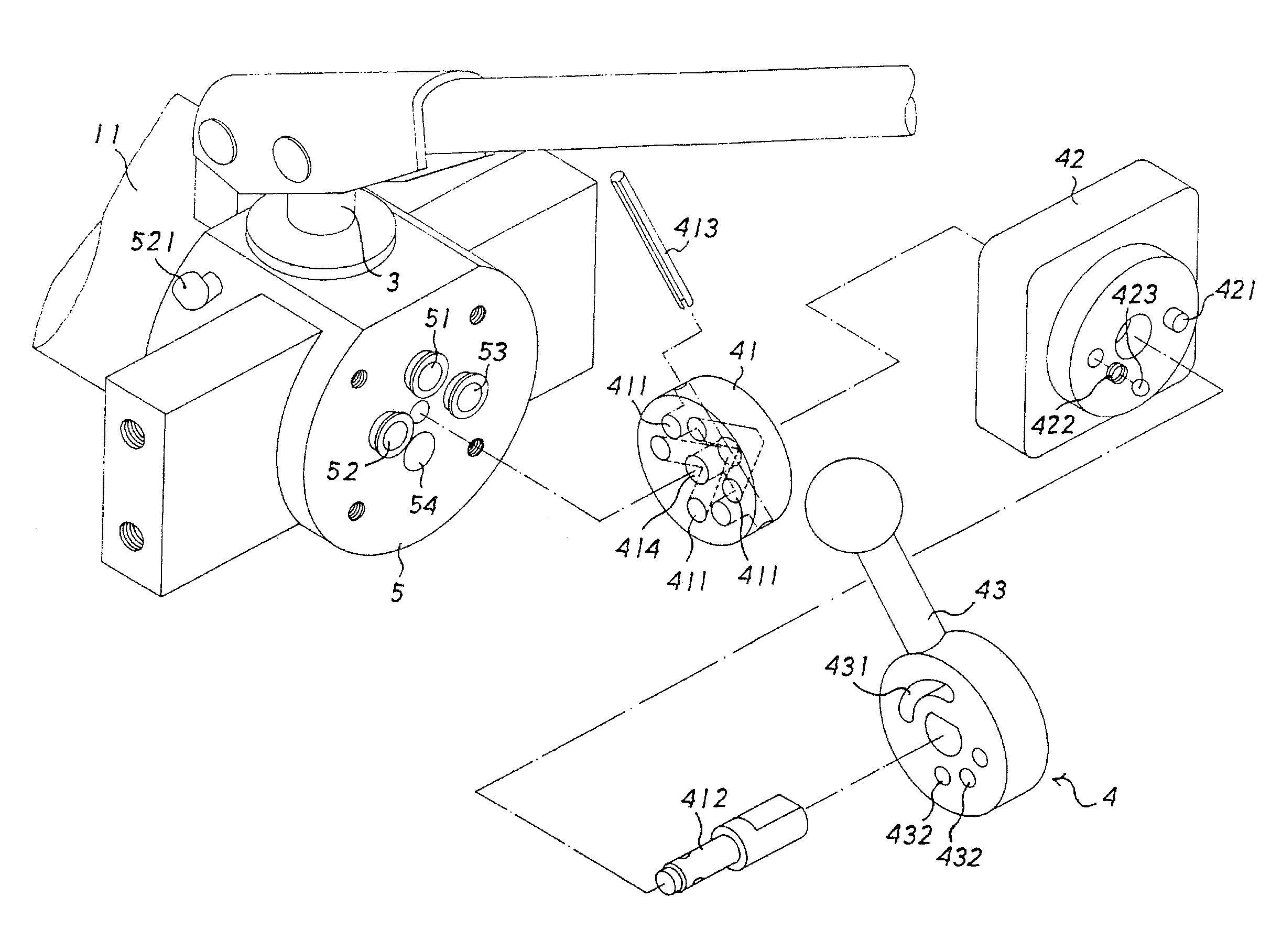
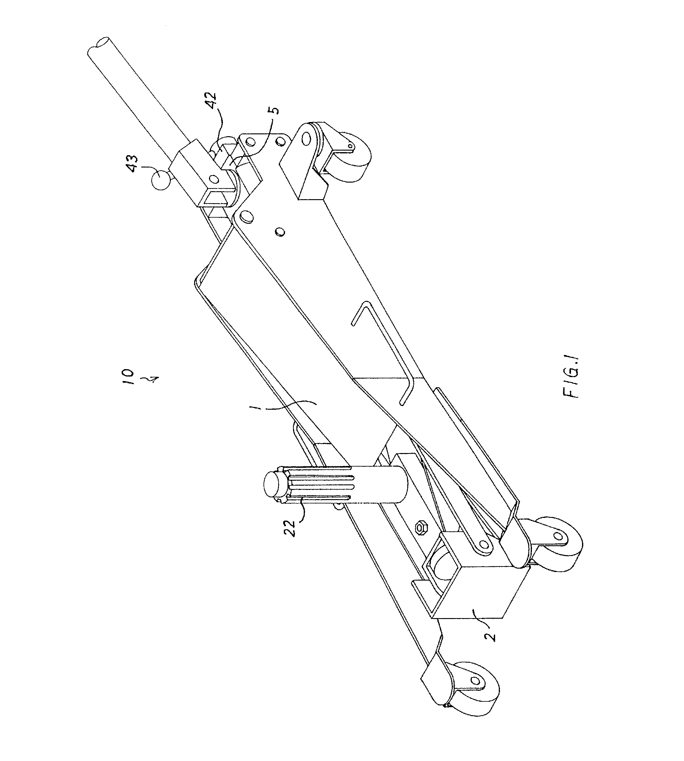
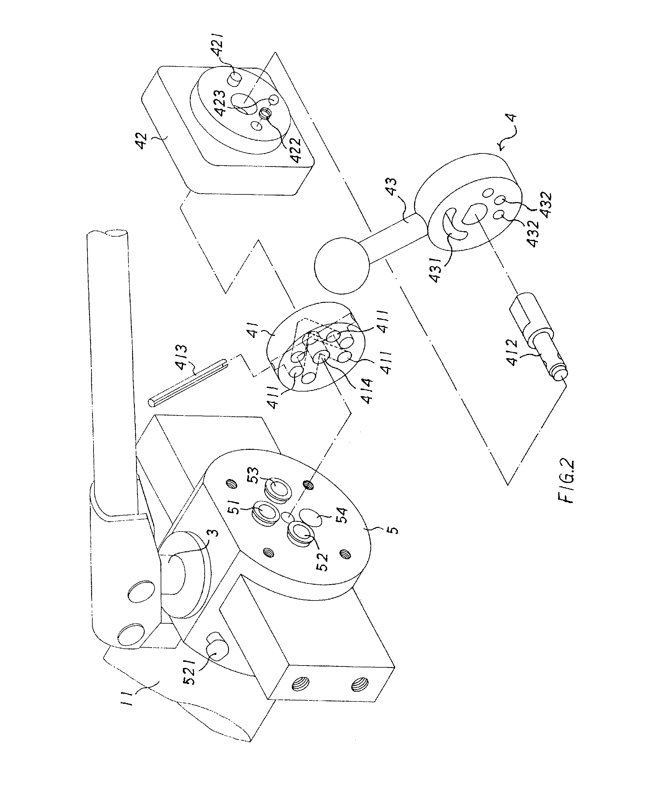
[0022]A jack structure 10 for a clutch according to a preferred embodiment of the present invention comprises a movable arm 1 to be pushed to move vertically by a main hydraulic cylinder 11, and a holder 2 including a support rod 22 axially disposed thereon to be actuated by an auxiliary hydraulic cylinder 21 of the movable arm 1 to move vertically and horizontally relative to the holder 2 (as shown in FIG. 1).

[0023]The main hydraulic cylinder 11 is a single acting hydraulic cylinder, and the auxiliary cylinder 21 is a double acting hydraulic cylinder. The main hydraulic cylinder 11 is in communication with an inlet tube 521 of the auxiliary hydraulic cylinder 21, and the auxiliary hydraulic cylinder 21 includes a piston with a larger diameter.

[0...


PUM


Abstract

A jack structure for a clutch contains a main hydraulic cylinder to push a movable arm to move vertically, and a holder including a support rod actuated by an auxiliary hydraulic cylinder of the movable arm to move vertically and horizontally relative to the holder. The main hydraulic cylinder is a single acting hydraulic cylinder, and the auxiliary cylinder is a double acting hydraulic cylinder. The main hydraulic cylinder communicates with an inlet tube of the auxiliary hydraulic cylinder. A valve seat includes a pump hole to draw hydraulic oil via a valve seat cylinder, an inlet connected with the inlet tube, an outlet coupled with an outlet tube of the auxiliary hydraulic cylinder, and a bore connected with an oil tank. A control post is axially connected with the valve seat and includes plural grooves to selectively communicate with the pump hole, the inlet, the outlet, and the bore after rotation.

Description

BACKGROUND OF THE INVENTION[0001]1. Field of the Invention[0002]The present invention relates to a jack structure for a clutch containing a main hydraulic cylinder to push a movable arm to move vertically, and a holder including a support rod axially disposed thereon to be actuated by an auxiliary hydraulic cylinder of the movable arm to move vertically and horizontally relative to the holder, such that the main and auxiliary hydraulic cylinders are actuated by the hydraulic oil outputted from the valve seat cylinder and the control post to retract simultaneously, so that the movable arm and the support rod move vertically and respectively.[0003]2. Description of the Prior Art[0004]A jack for a clutch serves as a lift structure when disassembling and assembling the clutch, and, accordingly, it is an auxiliary equipment in a vehicle maintenance factory.[0005]A conventional jack structure for the clutch is provided with a hydraulic cylinder to lift and disassemble the clutch easily so...

Claims


Application Information

Patent Timeline
Patent Type & Authority Patents(United States)
IPC IPC(8): B62B3/06A62B3/00B66F5/02B66F5/04B66F3/24E21D15/44B66F3/00B66F3/42
CPCB66F5/04
Inventor HSU, KUN-SHAN
Owner CHIN JIH SHERN INDAL
Why Eureka
Try Eureka