Magnetic sensing method, atomic magnetometer and magnetic resonance imaging apparatus
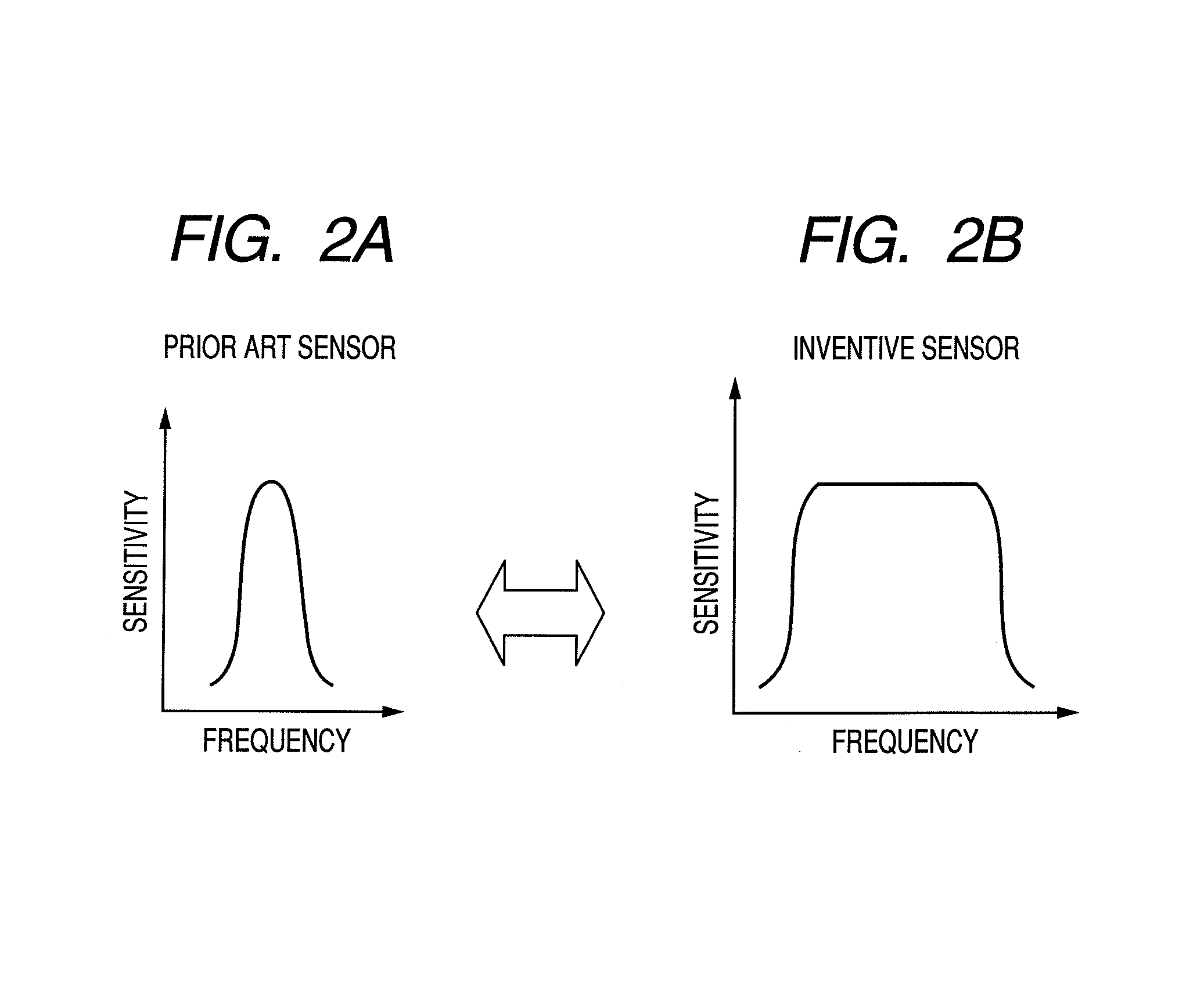
a magnetic resonance imaging and atomic magnetometer technology, applied in the field of magnetic sensing methods, atomic magnetometers and magnetic resonance imaging apparatuses, can solve the problems of inability to provide a good image quality, narrow measurement band, etc., and achieve the effect of extending the measurement frequency band
- Summary
- Abstract
- Description
- Claims
- Application Information
AI Technical Summary
Benefits of technology
Problems solved by technology
Method used
Image
Examples
first embodiment
Magnetic Sensing Method
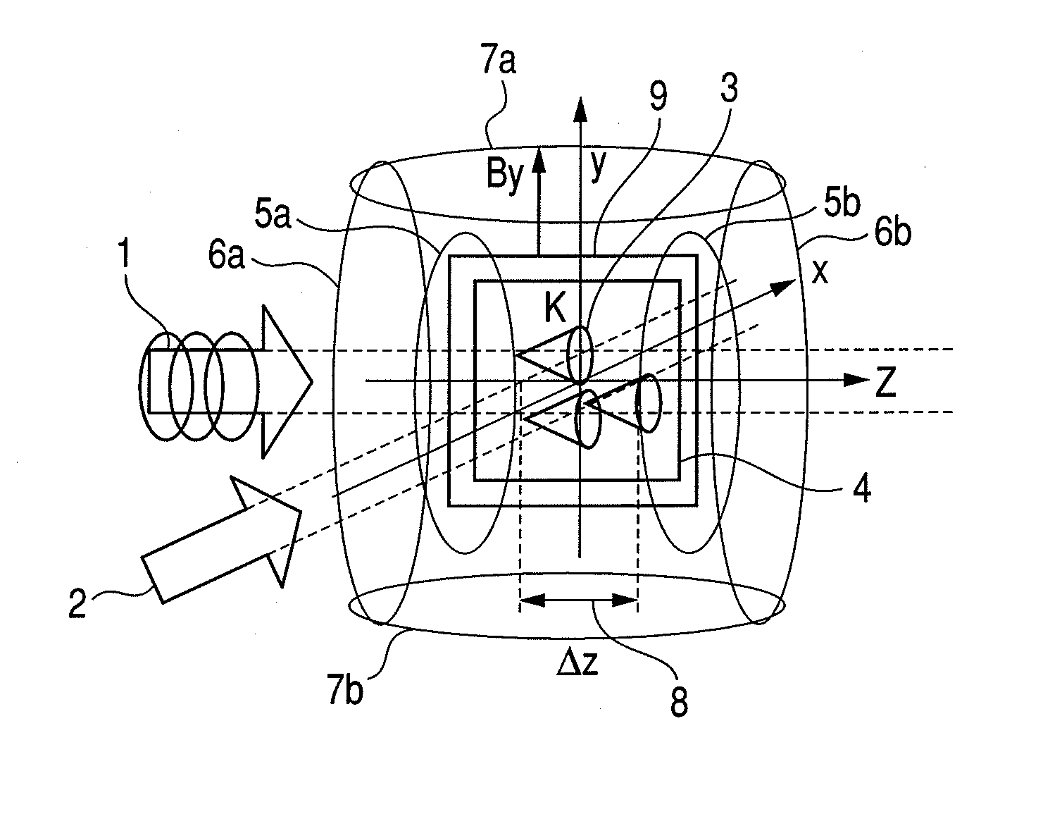
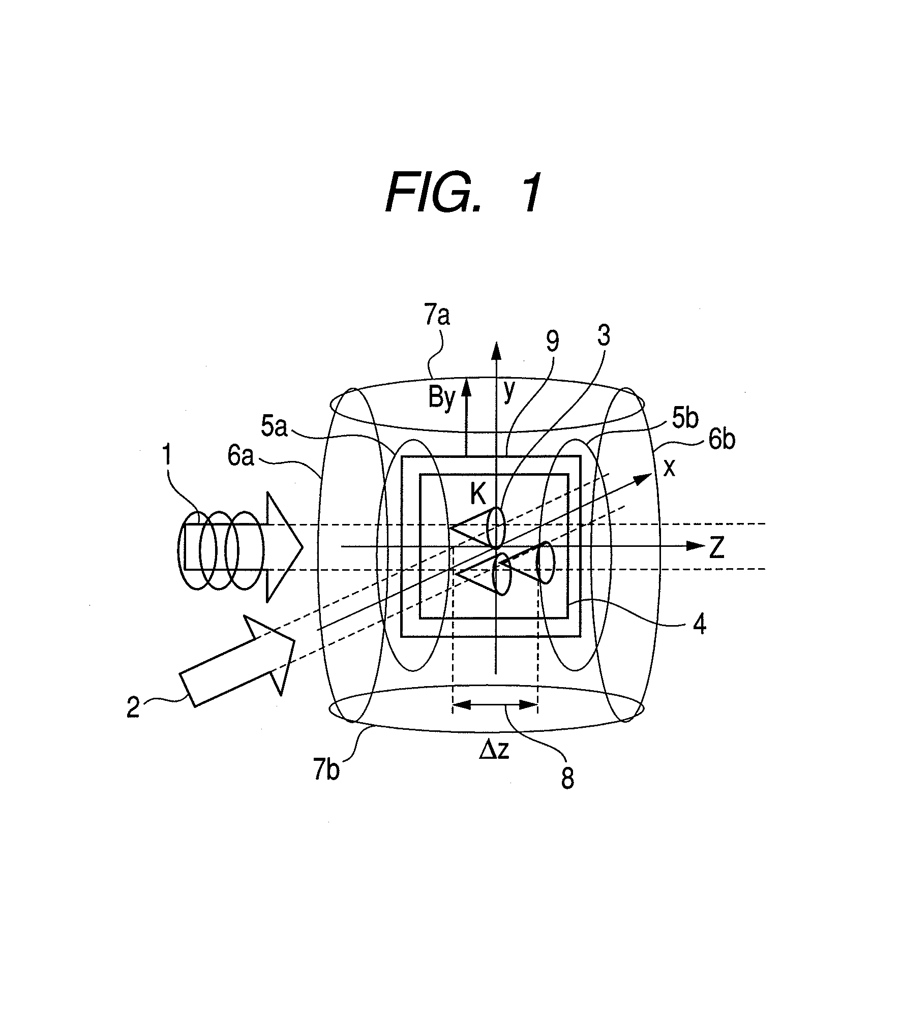
[0048]This embodiment of magnetic sensing method of the present invention has the following characteristics.
[0049]Specifically, a pump light having a circularly polarized component and a probe light having a linearly polarized component are irradiated onto a group of atoms (a mass of atoms) contained in a cell so as to make the lights produce an intersection region (or an intersection width). Then, a magnetic sensing operation is conducted by utilizing a change of rotation angle of a plane of polarization of the probe light before and after it passes the cell (which may also be expressed as a change in the angle of rotation in the direction of polarization). The pump light and the probe light are irradiated in a state where a magnetic field of the direction in which the pump light strikes the intersection region is provided with a gradient to acquire information relating to the change of rotation angle of the plane of polarization of the probe light before and...
second embodiment
[0071]The atomic magnetometer of this embodiment is formed so as to include a cell, a group of atoms contained in the cell, a light source for outputting a pump light having a circularly polarized component and a light source for outputting a probe light having a linearly polarized component.
[0072]The atomic magnetometer has a magnetic field application unit for applying a magnetic field gradient having a magnetic field intensity difference of not less than 4h(RSD+R) / (gμ) to an intersection region of the pump light and the probe light, where h is the Planck's constant, g is a g-factor, R is a pumping rate, RSD is a spin decay rate and μ is the Bohr magneton.
[0073]The atomic magnetometer of this embodiment may further include a rotation angle measurement unit that irradiates the pump light and the probe light onto the group of atoms contained in the cell so as to make them produce an intersection region and measures a change of rotation angle of a plane of polariza...
third embodiment
Magnetic Resonance Imaging Apparatus
[0078]The magnetic resonance imaging apparatus of this embodiment comprises the following components.
[0079]Specifically, it has an atomic magnetometer adapted to use the magnetic sensing method according to the present invention as described above by referring to the first embodiment of the present invention. It additionally has a gradient magnetic field generating coil for providing a gradient magnetic field different from the magnetic field for providing the intersection region with a magnetic field gradient and a magnetostatic field generating coil. It further includes an RF coil for irradiating an electromagnetic wave to the object of examination.
[0080]Any of the components of an ordinary magnetic resonance imaging apparatus may appropriately be used for this embodiment except that a resonance type atomic magnetometer as described above is employed as detection apparatus (receiving sensor) for receiving RF signals.
[0081]A gradient magnetic fie...
PUM
 Abstract
Description
Claims
Application Information
 - R&D
- Intellectual Property
- Life Sciences
- Materials
- Tech Scout
- Unparalleled Data Quality
- Higher Quality Content
- 60% Fewer Hallucinations
Browse by: Latest US Patents, China's latest patents, Technical Efficacy Thesaurus, Application Domain, Technology Topic, Popular Technical Reports.
© 2025 PatSnap. All rights reserved.Legal|Privacy policy|Modern Slavery Act Transparency Statement|Sitemap|About US| Contact US: help@patsnap.com


