Battery pack and cordless tool using the same

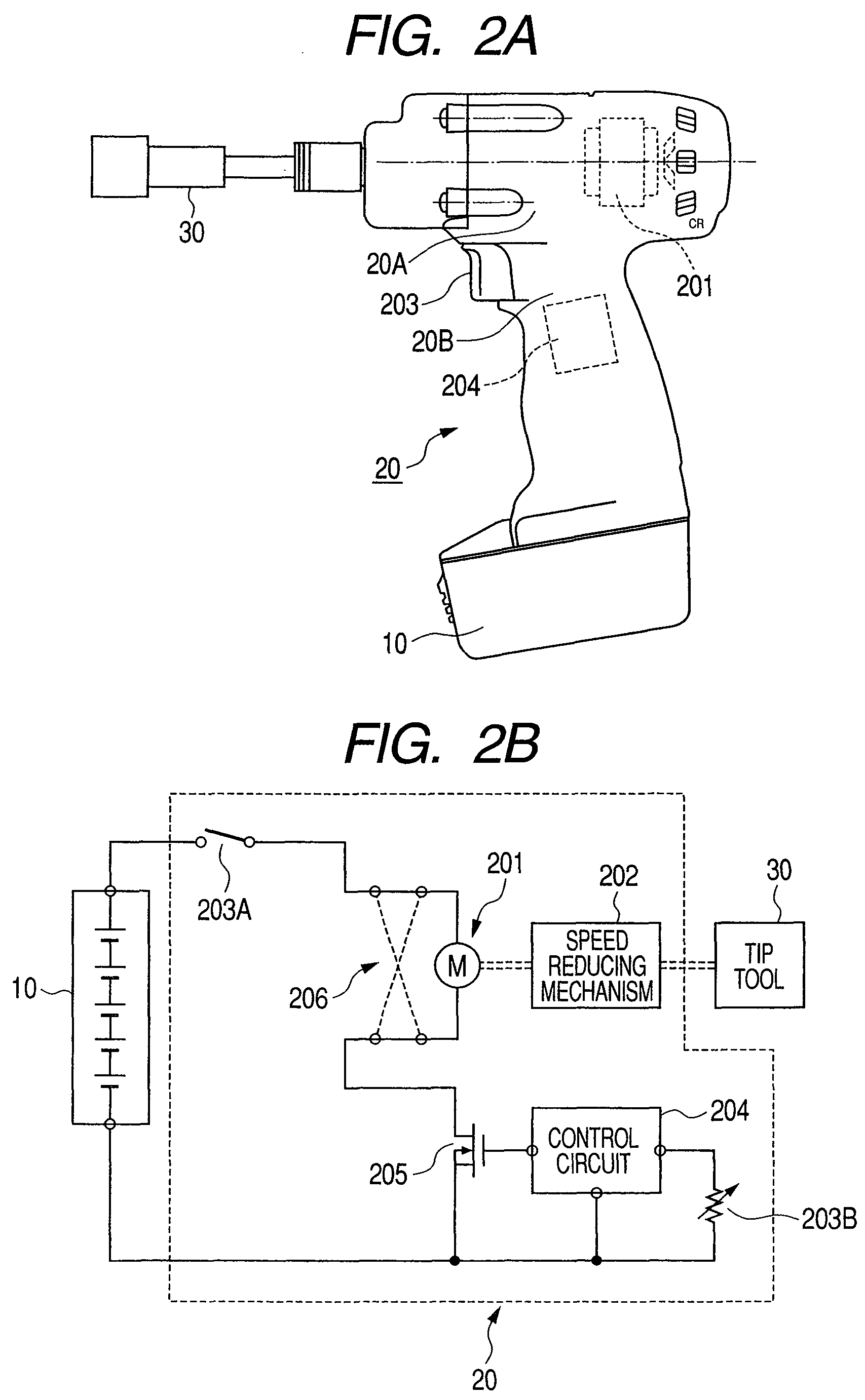
a battery pack and cordless technology, applied in the direction of cell components, cell component details, safety/protection circuits, etc., can solve the problems of overcurrent flowing into the battery, the fluctuations of the loading current through the motor 201/b> are naturally dangerous, and the battery may be damaged

Active Publication Date: 2013-02-26
KOKI HLDG CO LTD
View PDF27 Cites 34 Cited by
  • Summary
  • Abstract
  • Description
  • Claims
  • Application Information

AI Technical Summary

Benefits of technology

[0043]Specifically, an object of the invention is to solve the aforementioned technical problem (1) and to provide a battery device and a cordless electric tool, which do not damage the battery cells and the cell assembly, even if the load current of the motor is drastically fluctuated by the load fluctuations of the electric tool, and in which the battery cells and the cell assemblies are not damaged even if the cell assemblies of different charges are connected in parallel.
[0054]The following advantages are obtained according to the invention.(1) Since cell assemblies of an arbitrary number can be mounted on an electric tool, it is possible to provide a cordless electric tool, in which the user can select the current capacity (Ah).(2) Since the cell assemblies of an arbitrary number can be mounted on the electric tool, the user can adjust the weight of the electric tool.

Problems solved by technology

According to our investigations, it has been found that the following technical problems arise when the battery device using the aforementioned SCAT is employed in the cordless electric tool thus far described.
If the fluctuations of the load on the tool 30 are serious, the fluctuations of the loading current through the motor 201 are naturally so dangerous that an overcurrent may also flow into the battery device 10.

Method used


Image

  • Battery pack and cordless tool using the same
  • Battery pack and cordless tool using the same
  • Battery pack and cordless tool using the same

Examples


Embodiment Construction

[0071]The invention will be described on its embodiments consecutively in the order of (1) Constitution of Battery Device, (2) Constitution of Electric Tool Body, and (3) Constitution of Charger.

[0072](1) Constitution of Battery Device

[0073](1.1) Circuit Constitution

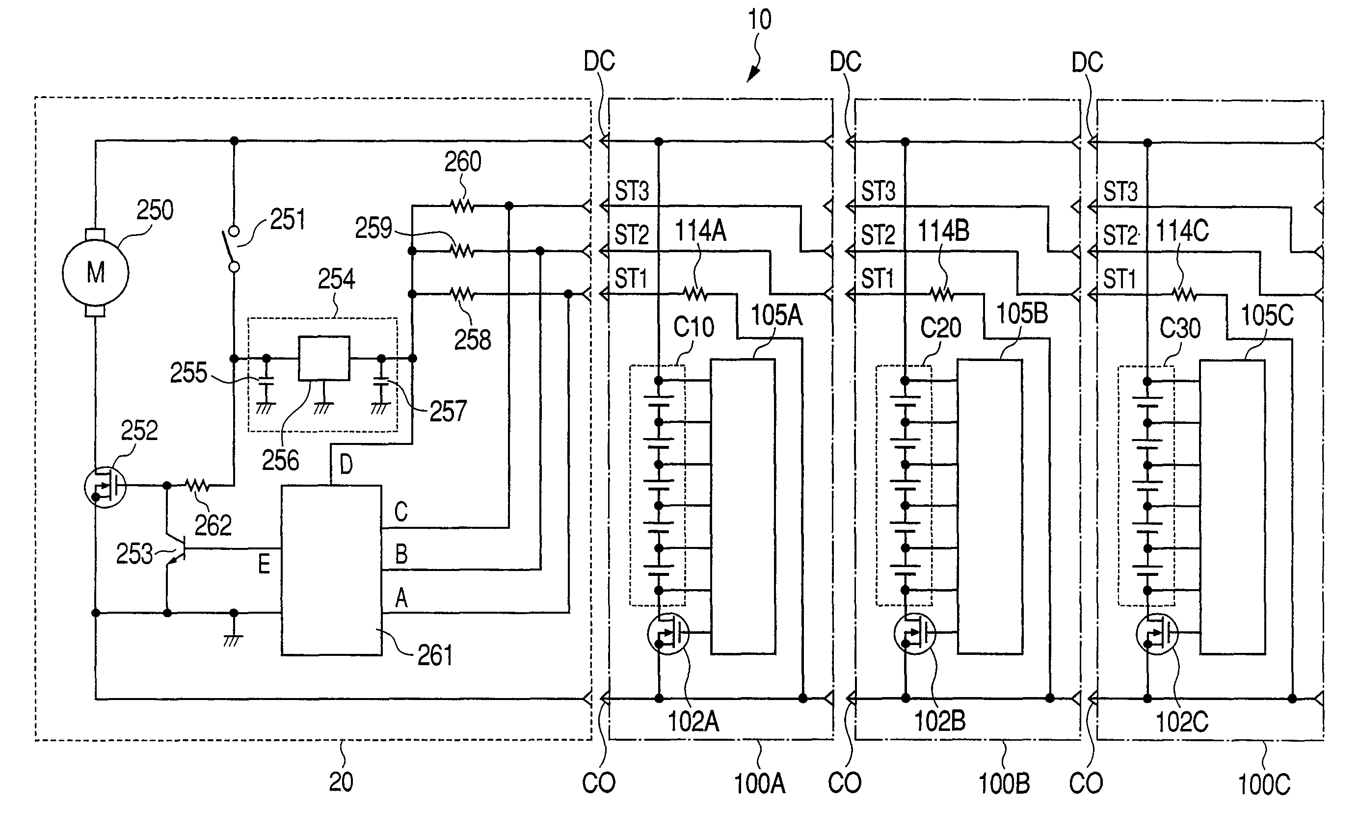
[0074]Here is described a cell assembly constituting the battery device according to the invention. FIG. 3 shows an electric circuit diagram, in which cell assemblies 100A and 100B are connected in parallel. The electric circuit of the cell assembly 100A is identical to that of 100B, and the following description is made only on the electric circuit of one cell assembly 100A.

[0075]In this embodiment, the cell assembly 100A includes five lithium cells C11 to C15 connected in series. These cells C11 to C15 will be called a cell group C10.

[0076]The cell group C10 has its positive terminal connected with a discharging positive terminal DC and its negative terminal connected with a common negative terminal C0 through a switch...


PUM

PropertyMeasurementUnit
electric currentaaaaaaaaaa
rated voltageaaaaaaaaaa
voltageaaaaaaaaaa

Abstract

A battery device is constituted by connecting such cell assemblies in parallel as each includes: a first cell group having a plurality of cells connected in series; a housing container for housing the first cell group; current detector housed in the container for detecting a current to flow through the first cell group; a switching element connected with the first cell group for turning ON / OFF the current to flow through the first cell group; and a controller for controlling the ON / OFF of the switching element in response to the output signal of the current detector.

Description

TECHNICAL FIELD[0001]The present invention relates to a battery device employing a stackable cell assembly technology (as will be abbreviated into the “SCAT”) and a cordless electric tool using the battery device.BACKGROUND ART[0002]First of all, the concept of the SCAT proposed by us is explained with reference to FIGS. 1A-1D.[0003]The cordless electric tool such as an electric driver, an electric drill or an impact tool is constituted to include a motor for generating a rotating power by reducing the speed of the motor by a speed reducing mechanism and then transmitting the rotating power to a tip tool.[0004]In FIG. 1A, numeral 20 designates a cordless electric tool, which is constituted to include a body trunk portion 20A and a handle portion 20B. A tool 30 is attached to the tip of the body trunk portion 20A. The handle portion 20B has its one end connected to the body trunk portion 20A and mounts a battery device 10 at its other end portion.[0005]All these cordless electric too...

Claims


Application Information

Patent Timeline
Patent Type & Authority Patents(United States)
IPC IPC(8): E21B1/14H01M50/51H01M50/512H01M50/522H01M50/574H01M50/583
CPCH01M2/1055H01M2/204H01M10/4207H02J7/00H01M10/482H02J7/0031H01M2/34H01M10/441H01M10/052Y02E60/10H01M50/213H02J7/00308H02J7/00304H01M50/522H01M50/583H01M50/512H01M50/51H01M50/574
Inventor HANAWA, HIROYUKIKATO, KIYOSHIFUNABASHI, KAZUHIKOOOMORI, KATSUHIRO
Owner KOKI HLDG CO LTD
Why Eureka
Try Eureka