
Method for performing burn-in test

a burnin test and burnin technology, applied in the field of burnin test, can solve the problems of increasing the anisotropic magnetic field (coercive force) of the magnetic recording medium, reducing the thermal stability of the magnetization of the magnetic particles, and reducing the number of evaluation processes and time. , to achieve the effect of reducing the number of evaluation processes and time, facilitating simultaneous conta

Active Publication Date: 2013-02-26
TDK CORPARATION
View PDF78 Cites 3 Cited by
  • Summary
  • Abstract
  • Description
  • Claims
  • Application Information

AI Technical Summary

Benefits of technology

The present invention is related to a method for simultaneously contacting a power supply probe to a large quantity of electrodes, and a light source element arrangement bar for holding multiple laser diodes. The invention aims to simplify the process of simultaneous contacting and to perform a burn-in test on a large number of laser diodes in a short time without causing damage to the elements. The technical effects of the invention include reducing the number of evaluation processes and time, maintaining a stable temperature in the light source element arrangement bar, and eliminating concentration of heat in defect parts.

Problems solved by technology

However, if the size of the magnetic particles is reduced, there is a problem that thermal stability for magnetization of the magnetic particles is lowered as the volume of the magnetic particles is reduced.
However, this increase in Ku causes an increase in anisotropic magnetic field (coercive force) of the magnetic recording medium.
As a result, when the anisotropic magnetic field of the magnetic recording medium exceeds an acceptable value determined from the upper value of the writing magnetic field intensity, writing becomes impossible.
With this type of thermally-assisted magnetic recording, a major issue is where and how a high output light source is installed in a magnetic head in order to provide sufficiently high intensity light stably at a desired position.
However, this type of burn-in test requires an extremely long time, such as from several hours to several tens of hours, in order to evaluate a single laser diode.
However, simultaneously contacting a power supply probe to a large quantity of electrodes for a plurality of laser diodes placed in a bar is extremely difficult.
Furthermore, even if a power supply probe can simultaneously contact with a large quantity of electrodes for a plurality of laser diodes as a result of an innovation in the configuration of the bar or the like for example, the following problems occur.
If such heat is not effectively dissipated to a fixture that contacts with the bar, the deviate of the LD chip temperature with regards to the test environment temperature is severe, and problems occurs in that an accurate evaluation is not possible.
There is concern that, in the worst case, large thermal stress is applied to the LD chip, and the chip itself is destroyed.
However, the structure of the fixture that incorporates the bar or the like becomes complex.

Method used


Image

  • Method for performing burn-in test
  • Method for performing burn-in test
  • Method for performing burn-in test

Examples


example

[0171]The present invention is described below in further detail by presenting a specific example.

[0172]A light source unit bar 71 was fabricated, on which 81 end surface emission type laser diodes which are the test subject are arranged.

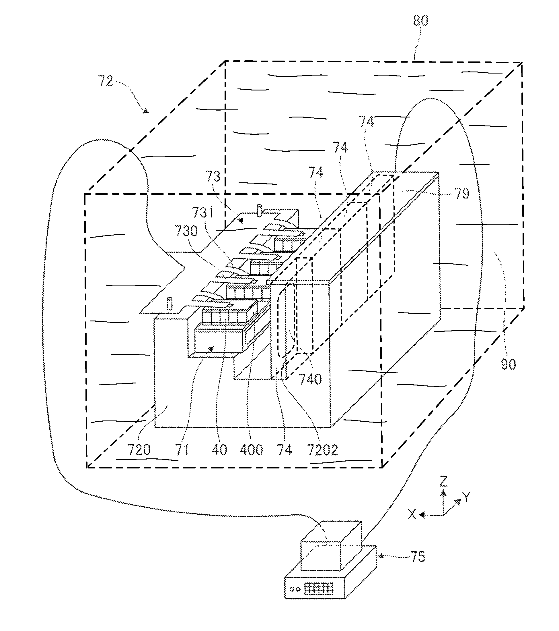
[0173]The light source unit bar 71 which is the subject of this test was assembled into a burn-in test device as illustrated in FIG. 7, and then the burn-in test was performed. A temperature sensor was inserted in the fixture stand below the installation part of the light source unit bar 71, and the temperature of the fixture stand was measured.

[0174]Naphthalene-based oil (product name: EXXSOL) was used as the insulation liquid. 81 laser diodes and 81 photodiodes were immersed in the insulation liquid. The test was to confirm the temperature rise. Therefore, the initial setting was low at 30° C. in order to make the effect easy to observe. When the 81 laser diodes were continuously electrified for 18 min., the temperature became approximately 33° C....


PUM


Abstract

A method of the invention for performing burn-in test includes assembling, on a fixture stand, a plurality of light source elements and a plurality of light detectors for monitoring a light output from a corresponding one of the plurality of light source elements; and electrifying the plurality of light source elements in a state where at least the plurality of light source elements and the plurality of light detectors are immersed in an insulation liquid. Thereby, it is realized to hold a stable temperature in a short period of time, to maintain a temperature that does not deviate from normal load conditions, and to perform a sorting test between defect parts and good part for light source unit chips without causing damage to the elements.

Description

BACKGROUND OF THE INVENTION[0001]1. Field of the Invention[0002]The present invention relates to a method for performing a burn-in test which is an effective conductivity test for screening elements. In particular, the present invention relates to a method for performing a burn-in test for a light source unit that is provided with a light source for thermally-assisted magnetic recording.[0003]2. Description of the Related Art[0004]In the field of magnetic recording using a head and a medium, further improvements have been demanded in performance of thin film magnetic heads and magnetic recording media in view of an increase in recording density of magnetic disk devices. For the thin film magnetic heads, composite type thin film magnetic heads configured from lamination of a reading magnetoresistive (MR) element and a writing electromagnetic conversion element are being widely used.[0005]The magnetic recording medium is a non-continuous medium, in which magnetic particles are aggrega...

Claims


Application Information

Patent Timeline
Patent Type & Authority Patents(United States)
IPC IPC(8): G01R31/308
CPCG11B5/455H01S5/0042G01R31/2635G01R31/2642H01S5/0021G11B2005/0021
Inventor SHIMAZAWA, KOJIHOSOI, RYOITO, YASUHIROKANEKO, MASAAKIHONDA, TAKASHIFUJII, RYUJIHOSAKA, KOJI
Owner TDK CORPARATION
Learn More