Method for configuring a finite impulse response filter in a programmable logic device

a programmable logic and filtering technology, applied in the field of configuring a finite impulse response filter in a programmable logic device, can solve the problems of difficult routing, and limiting the maximum clock speed attainable, and achieve the effect of greater efficiency

Inactive Publication Date: 2013-02-26
ALTERA CORP
View PDF381 Cites 12 Cited by
  • Summary
  • Abstract
  • Description
  • Claims
  • Application Information

AI Technical Summary

Benefits of technology

[0009]The present invention achieves greater efficiency in the configuration of specialized functional blocks of the type described above as FIR filters, by providing a configuration method that combines aspects of different forms of FIR filters in a way that is more efficient.

Problems solved by technology

Although Direct Form FIR filters map easily onto specialized functional blocks of the type described above—indeed, a 4-tap Direct Form FIR filter can be implemented entirely in one such block in the aforementioned STRATIX® family of devices—larger filters may require a long input sample chain and a large adder tree that is difficult to route and limits the maximum clock speed attainable.
However, the required adders become progressively wider down the chain (because the sum becomes wider as more stages are added in), with the result that a large number of adders have large widths, which limits the maximum clock speed attainable.
In addition, because each stage requires one multiplier and one adder (to add each product to the delayed sum of the upstream stages), Transpose Form FIR filters do not map well onto specialized functional blocks of the type described above, which generally have fewer adders than multipliers.

Method used


Image

  • Method for configuring a finite impulse response filter in a programmable logic device
  • Method for configuring a finite impulse response filter in a programmable logic device
  • Method for configuring a finite impulse response filter in a programmable logic device

Examples


Embodiment Construction

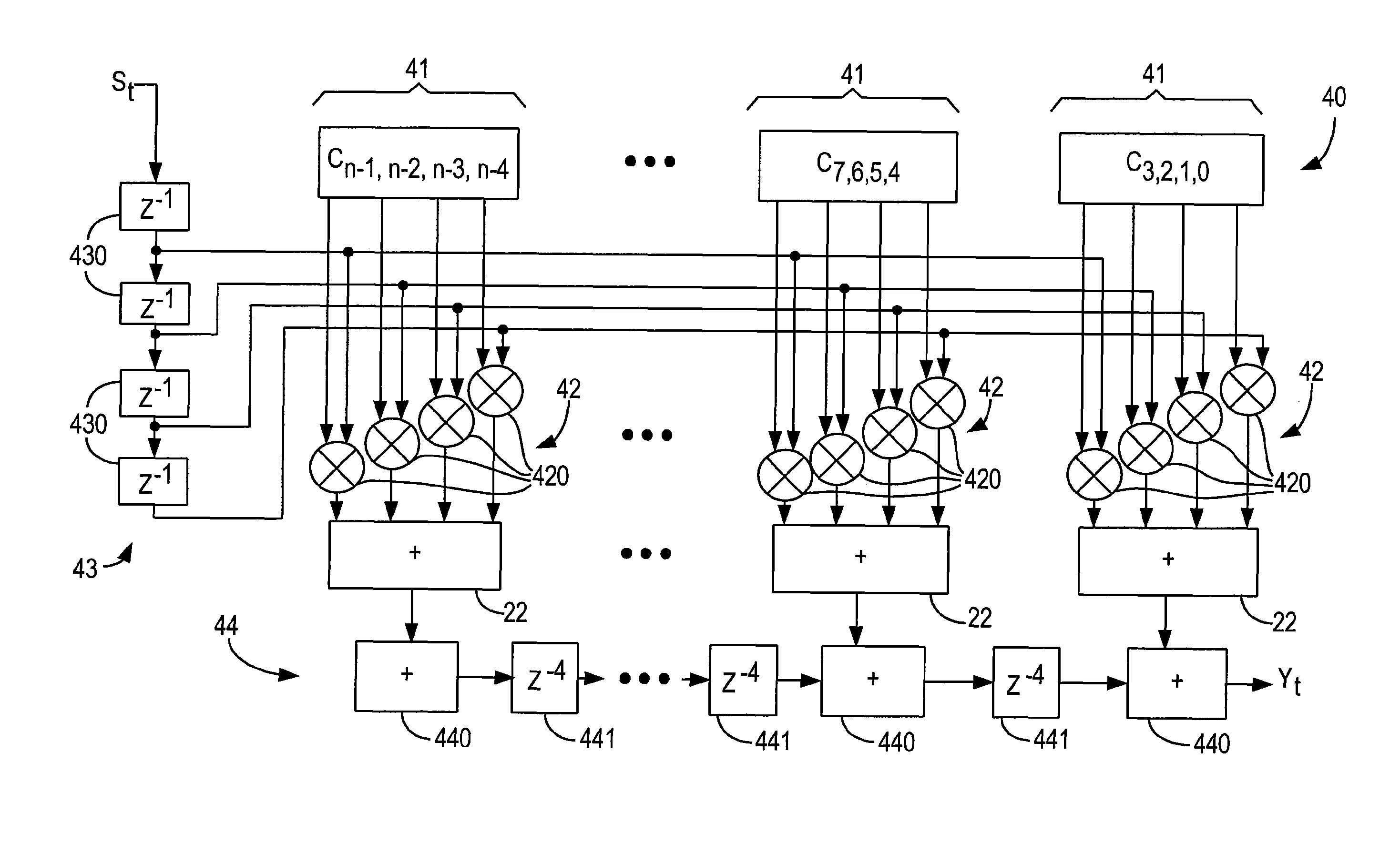
[0022]As described above, FIR filters are common structures used in many DSP applications. Mathematically, a FIR filter may be described as:

[0023]Yk=∑i=0Taps-1⁢⁢Ci⁢⁢•⁢⁢Sk-i

where Yk is the kth output term, ci is the ith coefficient, sk-i is the (k−i)th sample, and Taps is the number of taps in the filter.

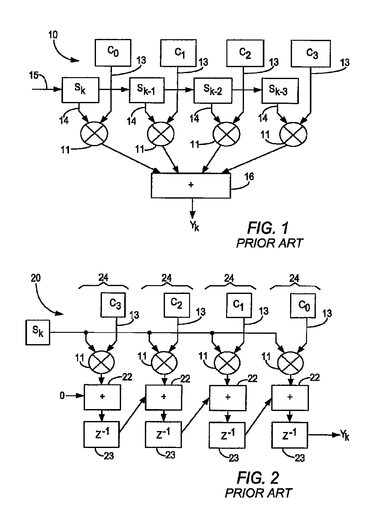
[0024]The structure of a 4-tap Direct Form II FIR filter 10 is shown in FIG. 1, and includes four multipliers 11. The multiplier outputs are added by adder tree 12, shown schematically in collapsed form, to provide term Yk. Each multiplier 11 has a coefficient input 13 for one of the four coefficients c0-c3. In some applications, the coefficients are held constant, while in others, such as adaptive filters, decimation filters, interpolation filters, etc., they may change. Each multiplier 11 also has a sample input 14, and the samples sk are clocked in via sample chain 15. The kth term Yk is provided when coefficient c0 is being multiplied by the kth sample sk and the other coefficien...


PUM


Abstract

A hybrid FIR filter includes a plurality of FIR filter units arranged as Direct Form FIR filters, connected together in an arrangement similar to a Transpose Form FIR filter. The hybrid filter arrangement may be used to configure a larger FIR filter in a programmable logic device having one or more specialized functional blocks, incorporating multipliers and adders, that are particularly well-suited for configuration as small Direct Form FIR filters.

Description

BACKGROUND OF THE INVENTION[0001]This invention relates to a method for configuring a finite impulse response filter in a programmable logic device, and more particularly to efficiently configuring a finite impulse response filter of arbitrary size.[0002]Programmable logic devices are well known. Early programmable logic devices were one-time configurable. For example, configuration may have been achieved by “blowing”—i.e., opening—fusible links. Alternatively, the configuration may have been stored in a programmable read-only memory. Those devices generally provided the user with the ability to configure the devices for “sum-of-products” (or “P-TERM”) logic operations. Later, such programmable logic devices incorporating erasable programmable read-only memory (EPROM) for configuration became available, allowing the devices to be reconfigured.[0003]Still later, programmable logic devices incorporating static random access memory (SRAM) elements for configuration became available. Th...

Claims


Application Information

Patent Timeline
Patent Type & Authority Patents(United States)
IPC IPC(8): G06F17/10
CPCH03H17/06
Inventor MAUER, VOLKERDEMIRSOY, SULEYMAN SIRRI
Owner ALTERA CORP
Why Eureka
Try Eureka