Particle beam therapy system and adjustment method for particle beam therapy system

a particle beam and therapy system technology, applied in the field adjustment method of particle beam therapy system, can solve the problems of large burden on patients, large increased damage to normal cells located at a shallower position than the tumor volume, so as to reduce the amount of irradiation, the difference distance of a charged particle beam is longer, and the irradiation flexibility is high.

Active Publication Date: 2013-03-05
MITSUBISHI ELECTRIC CORP
View PDF25 Cites 46 Cited by
  • Summary
  • Abstract
  • Description
  • Claims
  • Application Information

AI Technical Summary

Benefits of technology

[0019]In a particle beam therapy system according to the present invention, a scanning electromagnet is disposed at the upstream side of a deflection electromagnet for switching a beam orbit; therefore, by making the divergence distance of a charged particle beam longer, there can be obtained a particle beam therapy system, the irradiation flexibility of which is high and that can reduce the amount of irradiation onto a normal tissue.
[0020]In an adjustment method for a particle beam therapy system according to the present invention, a data string of irradiation control values is read for each beam orbit, and actual irradiation with a charged particle beam is performed; then, through the combination of the data string of actual irradiation position coordinates of a charged particle beam at the isocenter and the data string of the irradiation control values, unknown parameters of an inverse map model for control values are set based on the irradiation position coordinates; therefore, there can be obtained a particle beam therapy system that enables accurate irradiation, whatever orbit is selected.

Problems solved by technology

Accordingly, when it is tried to apply a sufficient dose to a tumor volume located in a deep position, there is caused larger damage to normal cells located at a shallower position than the tumor volume.
However, in the case of a horizontal-irradiation method utilizing a conventional chair-type patient holding apparatus, it is required to change the posture of the whole chair-type patient holding apparatus with a patient supported thereon, when irradiation angle is changed; therefore, there has been a problem that a burden is imposed on the patient.
For example, when the chair-type patient holding apparatus is slanted forward or laterally, a great deal of burden is imposed, especially on an aged patient.
However, this method requires a large system; thus, there has been problems that a great deal of initial cost (introduction cost) and running cost is required, that installation thereof needs a large space, and the like.
A particle beam therapy system equipped with a rotating gantry is commonly utilized in proton-beam therapy; however, in the case where a heavy ion such as a carbon ion is utilized as a charged particle, the curvature radius at a time when a beam orbit is bent is large and hence a large electromagnet is required to be rotated; thus, systemization becomes further difficult.
Even though multi-port irradiation can be performed by use of a rotating gantry, the irradiation apparatus is driven to rotate along with the rotating gantry when the irradiation angle is changed; therefore, there has been a problem that the irradiation angle cannot be changed unless an engineer enters the irradiation chamber and confirms that the irradiation apparatus and a patient do not collide with each other.
As a result, even in the case where irradiation onto the same irradiation subject is performed, the area of a body surface through which a charged particle beam passes becomes small in comparison with a case where the divergence angle is small; thus, the irradiation density on the body surface becomes large, whereby damage to the body surface, which is a normal tissue, increases.

Method used


Image

  • Particle beam therapy system and adjustment method for particle beam therapy system
  • Particle beam therapy system and adjustment method for particle beam therapy system
  • Particle beam therapy system and adjustment method for particle beam therapy system

Examples


embodiment 1

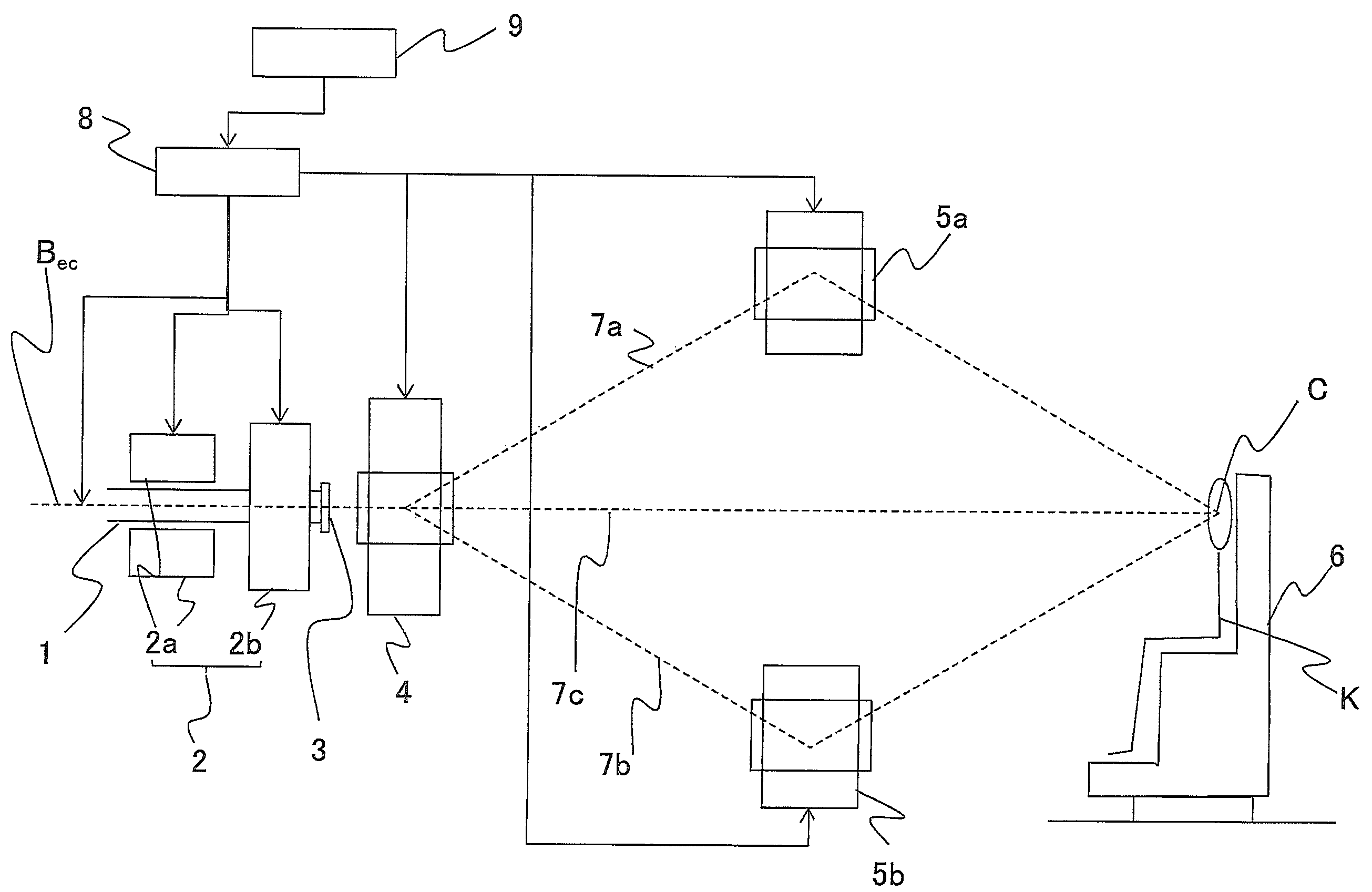
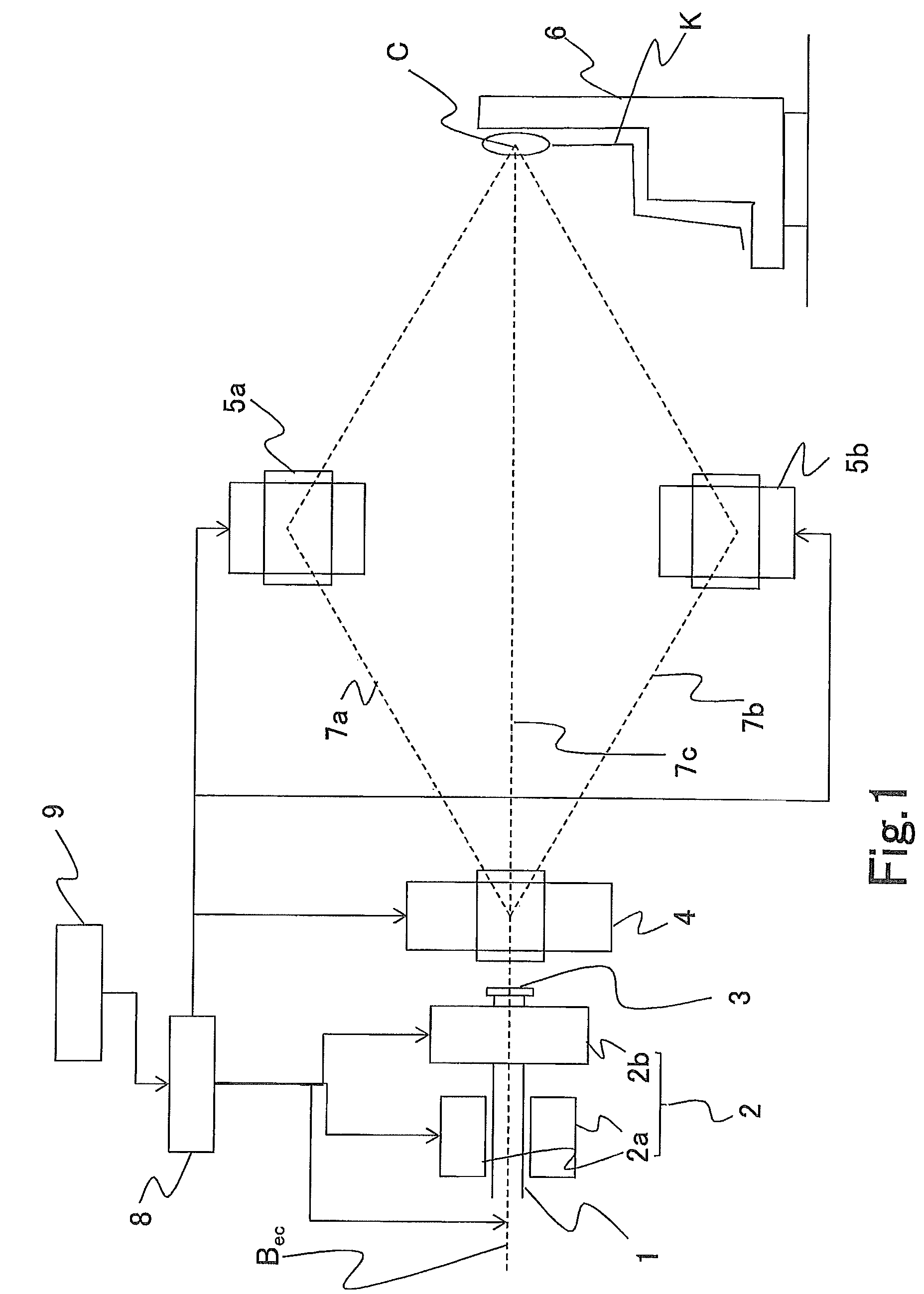
[0033]Embodiment 1 of a particle beam therapy system according to the present invention will be explained below. FIGS. 1 and 2 are diagrams for explaining a particle beam therapy system according to Embodiment 1 of the present invention. FIG. 1 is a diagram illustrating the overall configuration of a particle beam therapy system; FIG. 2 is a block diagram illustrating the function of a particle beam therapy system. As illustrated in FIG. 1, the particle beam therapy system includes a beam transport duct 1 for transporting an accelerated charged particle beam Bec without diffusing it; a scanning electromagnet 2 (2a and 2b) that is disposed outside the beam transport duct 1 in such a way that the beam transport duct 1 are inserted therein, and that performs scanning with the transported charged particle beam Bec; a beam outlet window 3 for extracting the charged particle beam Bec with which scanning has been performed; a deflection electromagnet 4 that is disposed at the downstream si...

embodiment 2

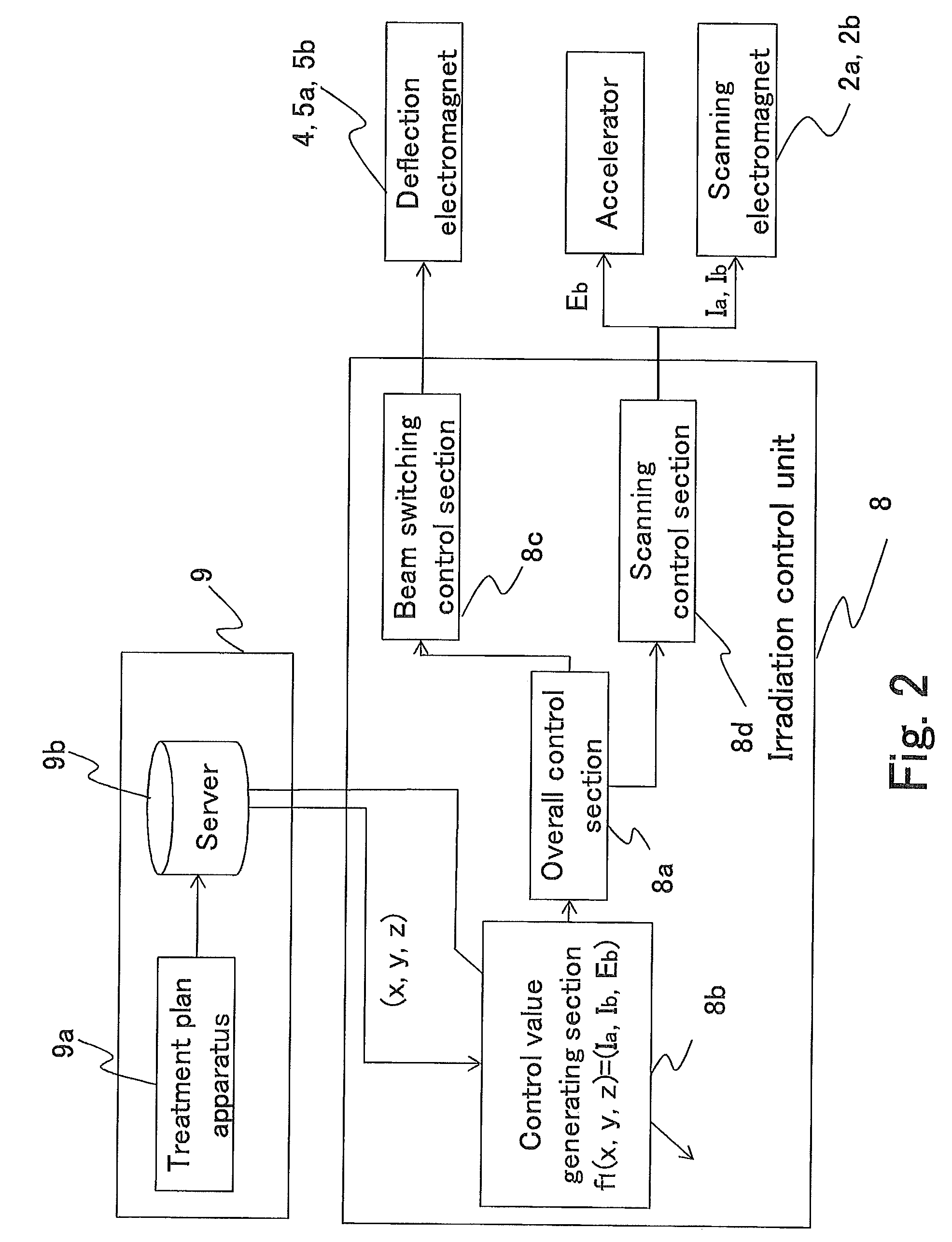
[0049]A particle beam therapy system and an adjustment method for a particle beam therapy system according to Embodiment 2 of the present invention will be explained below. FIGS. 3 and 4, and FIG. 5 are diagrams and a flowchart, respectively, for explaining a particle beam therapy system and an adjustment method for a particle beam therapy system according to Embodiment 2 of the present invention; FIG. 3 is a diagram illustrating the overall configuration of a particle beam therapy system; FIG. 4 is a block diagram illustrating the function of a particle beam therapy system; FIG. 5 is a flowchart representing an adjustment method for a particle beam therapy system. In the particle beam therapy system according to Embodiment 2, there will be described in detail the fact that, as a function of calculating, in accordance with a beam orbit, three-dimensional irradiation control values (Ia, Ib, Eb) from the point sequence data of target irradiation coordinates (x, y, z) for forming an ir...

example of embodiment 2

Variant Example of Embodiment 2

[0074]In Embodiment 2, there has been described an example where irradiation control values are read as a data string when calibration is implemented, and actual irradiation is performed for the read data string (the steps S100 through S200 in FIG. 5); however, in the case where the respective variants of the control values are changed every interval, calibration may be implemented according to the sequence represented in FIG. 6. FIG. 6 is a flowchart representing an example in which the process corresponding to the steps S100 through S200 in FIG. 5 has been varied; because being the same as processes in FIG. 5, the process before the step S20 and the process after the step S210 are omitted.

[0075]In the first place, the energy control value Eb, for a charged particle beam Bec, which mainly effects the z direction (the depth) is set to an initial value (e.g., Eb1 in Eb1, Eb2, . . . , Ebr) (the step S1010). Next, the control value Ib of the scanning elec...


PUM


Abstract

The objective is to obtain a particle beam therapy system, the irradiation flexibility of which is high and that can reduce the amount of irradiation onto a normal tissue. There are provided a scanning electromagnet that performs scanning and outputting in such a way that a supplied charged particle beam is formed in a three-dimensional irradiation shape based on a treatment plan; and deflection electromagnets that switch the orbits for the charged particle beam in such a way that the charged particle beam with which scanning and outputting are performed by the scanning electromagnet reaches an isocenter through a single beam orbit selected from a plurality of beam orbits established between the isocenter and the scanning electromagnet. The distance between the scanning electromagnet and the isocenter is made long.

Description

TECHNICAL FIELD[0001]The present invention relates to a particle beam therapy system that irradiates a proton beam or a heavy ion beam for the purpose of treating a cancer or the like and to an adjustment method for a particle beam therapy system; the present invention relates particularly to a particle beam therapy system utilizing a scanning-type irradiation method such as a spot-scanning method or a raster-scanning method.BACKGROUND ART[0002]When an X ray or a gamma ray is irradiated from the outside of a body, the dose becomes maximum in the vicinity of the surface of the body, and then the dose decreases as the depth increased. Accordingly, when it is tried to apply a sufficient dose to a tumor volume located in a deep position, there is caused larger damage to normal cells located at a shallower position than the tumor volume. In contrast, in the case of particle-beam irradiation, irradiation energy determines the depth of a position, in a body, at which a particle beam can ar...

Claims


Application Information

Patent Timeline
Patent Type & Authority Patents(United States)
IPC IPC(8): H01J1/50
CPCA61N5/1042A61N5/1043A61N5/1078H01J3/22H01J3/26A61N5/1077A61N2005/1087
Inventor HARADA, HISASHIIWATA, TAKAAKI
Owner MITSUBISHI ELECTRIC CORP
Why Eureka
Try Eureka