Coil arrangement for an electromagnetic tracking system

a coil arrangement and electromagnetic tracking technology, applied in the field of asymmetric coil arrangement can solve the problems of affecting the accuracy performance of electromagnetic tracking systems, processors performing processing cannot resolve the rotational orientation (roll) of coils, and the limited range of electromagnetic tracking systems

Active Publication Date: 2013-03-05
STRYKER EURO OPERATIONS HLDG LLC
View PDF165 Cites 51 Cited by
  • Summary
  • Abstract
  • Description
  • Claims
  • Application Information

AI Technical Summary

Benefits of technology

[0012]In an embodiment, a method of maximizing the tracking accuracy of an electromagnetic tracking system comprising attaching a first large coil and a second small coil to an object to be tracked; and determining the position and orientation of the object to be tracked.

Problems solved by technology

Electromagnetic tracking systems may be limited by the number of degrees of freedom they are able to track.
The processor performing the processing cannot resolve the rotational orientation (roll) of the coil.
However, having two coils in close proximity may introduce “mutual inductance coupling” into the mix.
Mutual inductance coupling between coils can negatively impact accuracy performance of an electromagnetic tracking system because cross-coupling currents cannot be accurately measured.
This unwanted current makes distinguishing the two coils' magnetic fields more difficult.

Method used


Image

  • Coil arrangement for an electromagnetic tracking system
  • Coil arrangement for an electromagnetic tracking system
  • Coil arrangement for an electromagnetic tracking system

Examples


Embodiment Construction

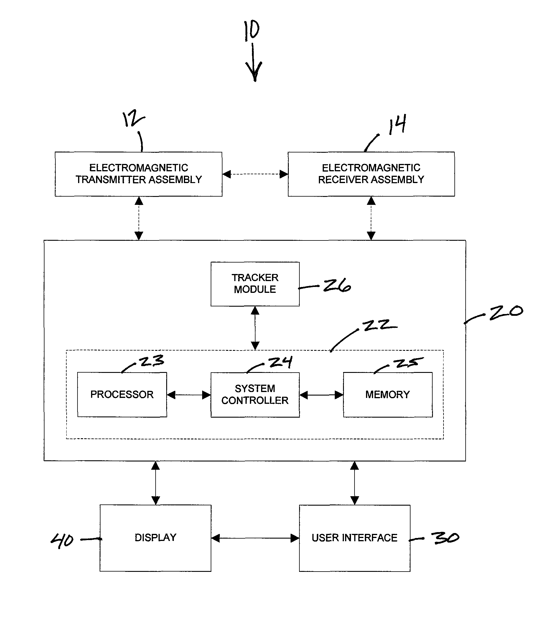
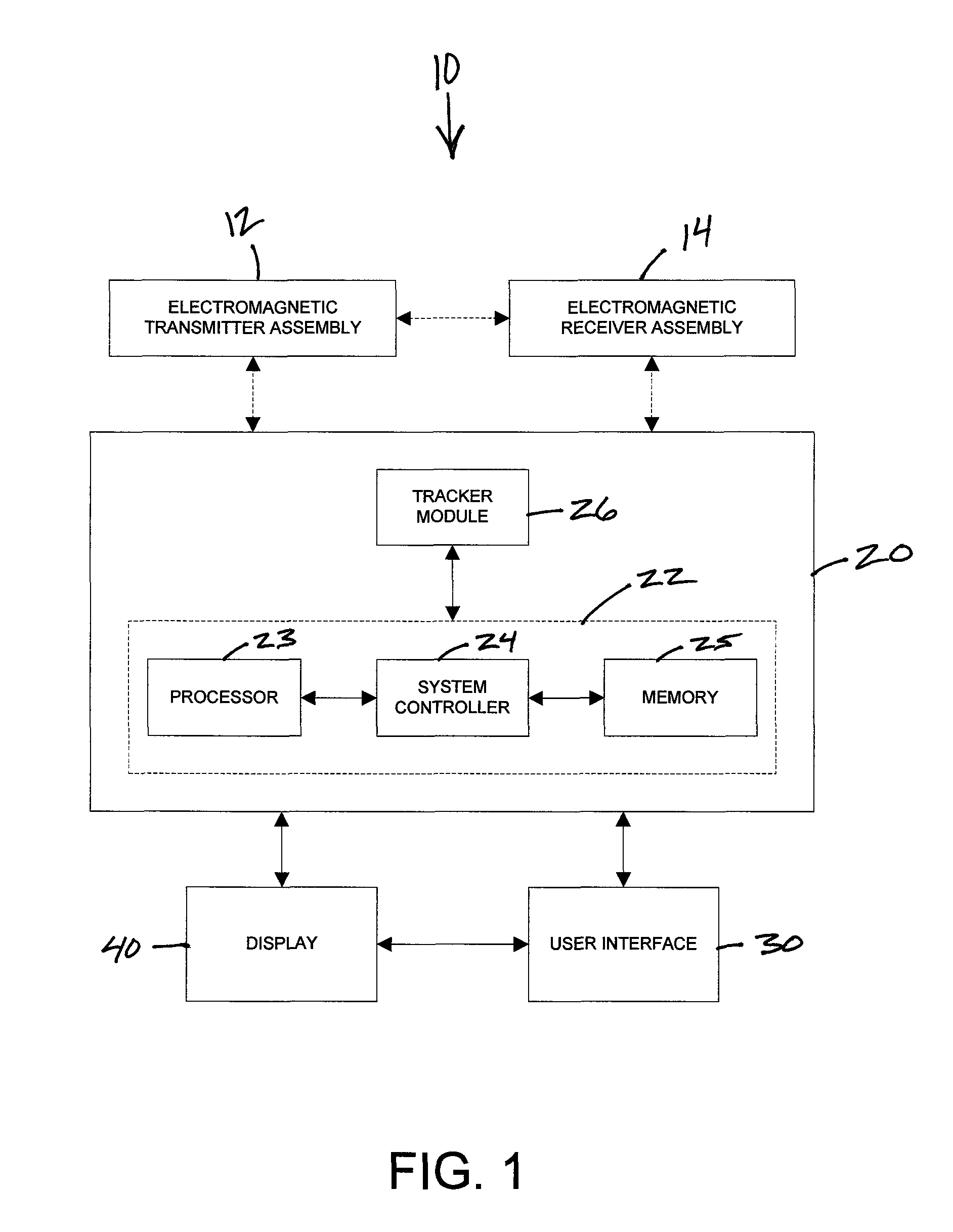
[0018]Referring now to the drawings, FIG. 1 is a block diagram illustrating an exemplary embodiment of an electromagnetic tracking system 10. The electromagnetic tracking system 10 comprises at least one electromagnetic transmitter assembly 12 with one or more transmitter coils and at least one electromagnetic receiver assembly 14 with one or more receiver coils. The transmitter or receiver coils are arranged to maximize the tracking accuracy and measure six degrees of freedom of the position and orientation of a medical device, implant or instrument.

[0019]The electromagnetic tracking system 10 further comprises a tracker workstation 20 coupled to and receiving data from the at least one electromagnetic transmitter assembly 12 and the at least one electromagnetic receiver assembly 14, a user interface 30 coupled to the tracker workstation 20, and a display 40 for visualizing imaging and tracking data. The tracker workstation 20 includes a tracking system computer 22 and a tracker mo...


PUM


Abstract

An electromagnetic tracking system comprising at least one electromagnetic transmitter assembly or at least one electromagnetic receiver assembly with two coils attachable to a trackable object to be tracked. The two coils including a first large coil and a second small coil, with the second small coil positioned asymmetrically with respect to the first large coil. The electromagnetic tracking system enables a medical professional to continually track the position and orientation of the object during a medical procedure.

Description

BACKGROUND OF THE INVENTION[0001]This disclosure relates generally to an electromagnetic tracking system that uses electromagnetic fields to determine the position and orientation of an object, and more particularly to an asymmetrical coil arrangement for an electromagnetic tracking system.[0002]Electromagnetic tracking systems have been used in various industries and applications to provide position and orientation information relating to objects. For example, electromagnetic tracking systems may be useful in aviation applications, motion sensing applications, retail applications, and medical applications. In medical applications, electromagnetic tracking systems have been used to provide an operator (e.g., a physician, surgeon, or other medical practitioner) with information to assist in the precise and rapid positioning of a medical device, implant or instrument located in or near a patient's body during image-guided surgery. An electromagnetic tracking system provides positionin...

Claims


Application Information

Patent Timeline
Patent Type & Authority Patents(United States)
IPC IPC(8): A61B5/05
CPCA61B19/5244G01R33/00A61B2019/5251A61B34/20A61B2034/2051
Inventor ANDERSON, PETER TRANEUS
Owner STRYKER EURO OPERATIONS HLDG LLC
Why Eureka
Try Eureka