Electric traction drives

a technology of electric traction and drive shaft, applied in the direction of gearing details, vehicle sub-unit features, gearing, etc., can solve the problems of increasing the cost of electronic controllers, increasing the cost and complexity of electronic controllers, and motors alone cannot produce constant power

Inactive Publication Date: 2013-03-12
FALLBROOK INTPROP COMPANY
View PDF477 Cites 95 Cited by
  • Summary
  • Abstract
  • Description
  • Claims
  • Application Information

AI Technical Summary

Problems solved by technology

However, a motor by itself cannot produce constant power when operating at a speed below its rated power.
This is undesirable because the motor becomes larger and more expensive than necessary for typical operating conditions.
The electronic controller also increases expense and complexity.
However, this increases cost, size, weight, and makes the motor more difficult to package with the machine it powers.

Method used


Image

  • Electric traction drives
  • Electric traction drives
  • Electric traction drives

Examples


Embodiment Construction

” one will understand how the features of the system and methods provide several advantages over traditional systems and methods.

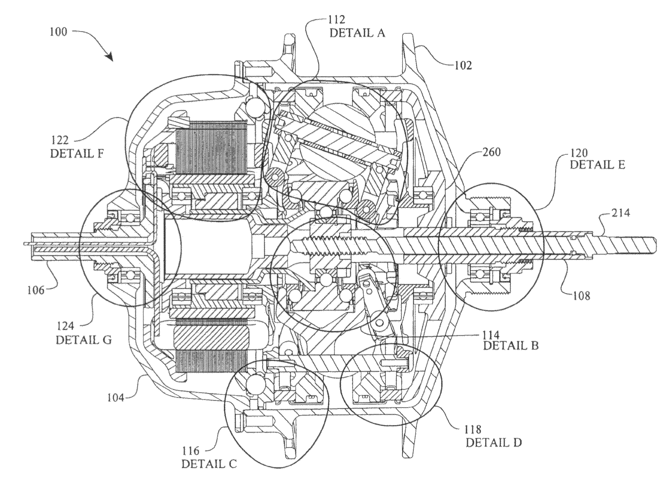
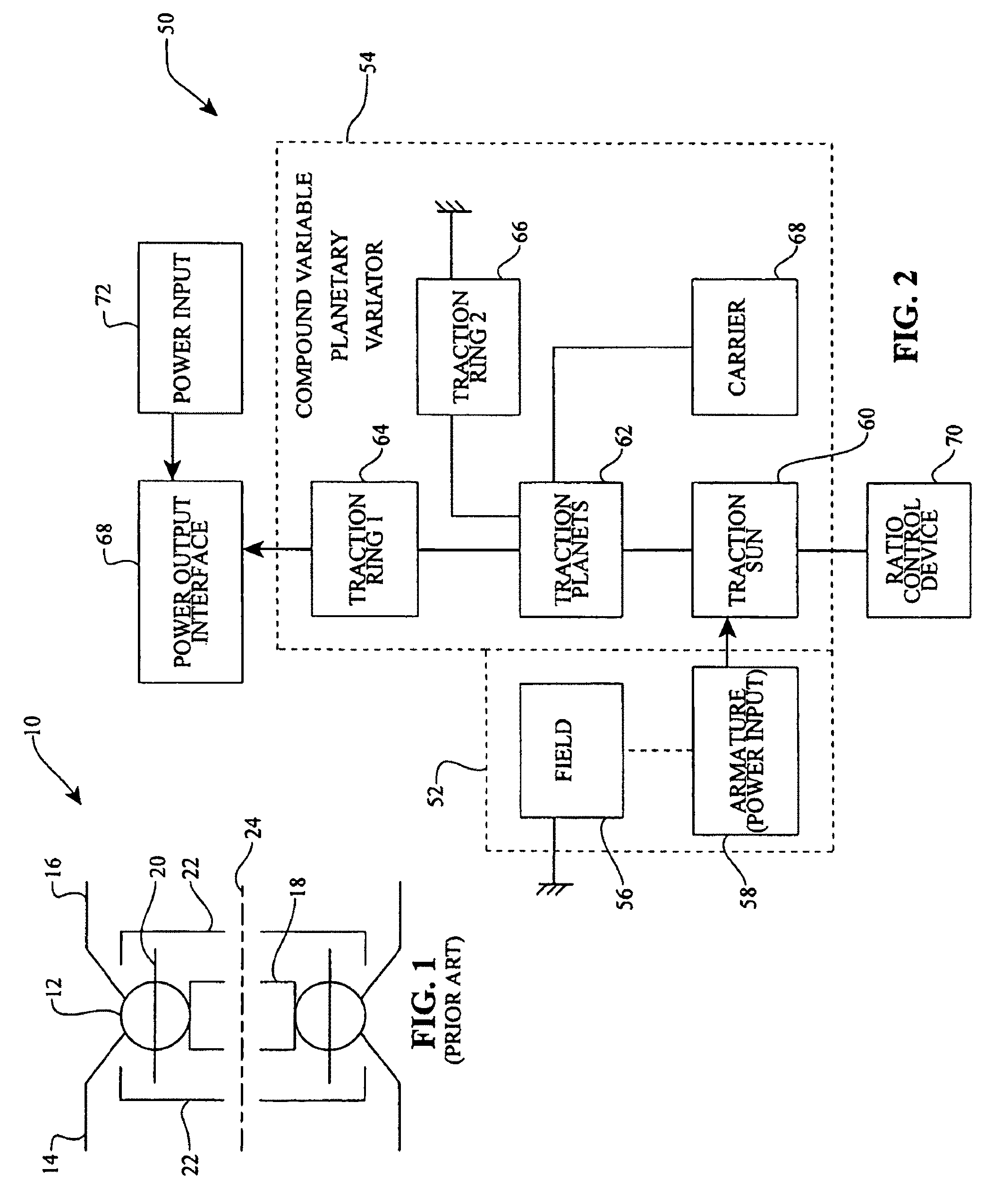
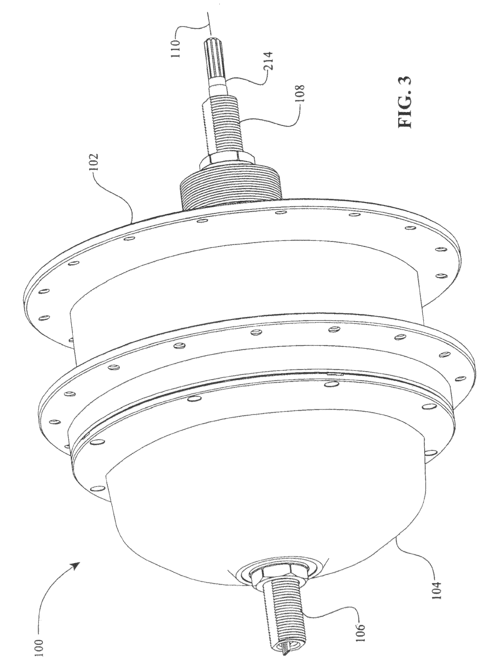
[0009]One aspect of the invention relates to an electric traction having a longitudinal axis and a group of traction planets distributed radially about the longitudinal axis. Each traction planet can be configured to rotate about a tiltable axis. The electric traction drive includes a first traction ring in contact with each of the traction planets, and includes a traction sun rotatable about the longitudinal axis. In one embodiment, the traction sun is positioned radially inward of and in contact with each of the traction planets, and the traction sun is capable of transferring power. The electric traction drive also includes a second traction ring in contact with each of the traction planets. In one embodiment, the electric traction drive includes an electricity producing generator having a set of non-rotating field windings coupled to a non-rotating com...


PUM


Abstract

Inventive embodiments are directed to components, subassemblies, systems, and / or methods for electric traction drives employing a continuously variable transmission (CVT) having a variator provided with a plurality of tilting traction planets and opposing traction rings. In one embodiment, an electric traction drive is provided with an electromotive device configured to transfer power to or from a traction sun of a CVT, In other embodiments, an electric traction drive is provided with an electromotive device that couples to certain components of a CVT such as a traction ring, a carrier assembly, and a main axle. Various inventive shifting assemblies having shift cams and shift cam cages can be used to facilitate adjusting the transmission speed ratio of a CVT. Various related devices include embodiments of, for example, a power input apparatus, a speed ratio shifter, a shift cam actuator, a shift nut, and a carrier assembly configured to support the tilting traction planets.

Description

RELATED APPLICATIONS[0001]This application claims the benefit of, and hereby incorporates by reference herein in its entirety, U.S. Provisional Applications 60 / 913,771, filed on Apr. 24, 2007, and 60 / 915,872, filed on May 3, 2007.BACKGROUND OF THE INVENTION[0002]1. Field of the Invention[0003]The field of the inventive embodiments disclosed here relates generally to systems and methods for electromechanical or electromotive drives, and more particularly the inventive embodiments relate to drives that use methods and assemblies that incorporate electrical device components and continuously or infinitely variable transmission components.[0004]2. Description of the Related Art[0005]To provide a continuously variable transmission (CVT) or an infinitely variable transmission (IVT), various traction roller transmissions in which power flows through traction rollers between torque input and output rings have been developed. In such transmissions, the traction rollers mount on structures th...

Claims


Application Information

Patent Timeline
Patent Type & Authority Patents(United States)
IPC IPC(8): F16H13/08
CPCF16H15/52B62M6/65F16H15/50F16H57/021F16H63/30F16H37/086F16H15/28B62M11/16B60K17/12B60Y2400/60B60Y2400/72B60Y2400/73H02K7/116H02K19/16
Inventor POHL, BRAD P.
Owner FALLBROOK INTPROP COMPANY
Why Eureka
Try Eureka