Method and apparatus for generating nuclear fusion using crystalline materials

a technology of crystalline materials and nuclear fusion, applied in the field of fusion research, can solve the problems of deep skepticism of attempts to produce fusion in a room temperature solid-state setting, including fusion and “bubble” fusion, and achieve the effect of reducing the risk of fusion

Inactive Publication Date: 2013-03-12
RGT UNIV OF CALIFORNIA
View PDF9 Cites 2 Cited by
  • Summary
  • Abstract
  • Description
  • Claims
  • Application Information

AI Technical Summary

Problems solved by technology

However, attempts to produce fusion in a room temperature solid-state setting, including “cold” fusion and “bubble” fusion, have met with deep skepticism.

Method used


Image

  • Method and apparatus for generating nuclear fusion using crystalline materials
  • Method and apparatus for generating nuclear fusion using crystalline materials
  • Method and apparatus for generating nuclear fusion using crystalline materials

Examples


example

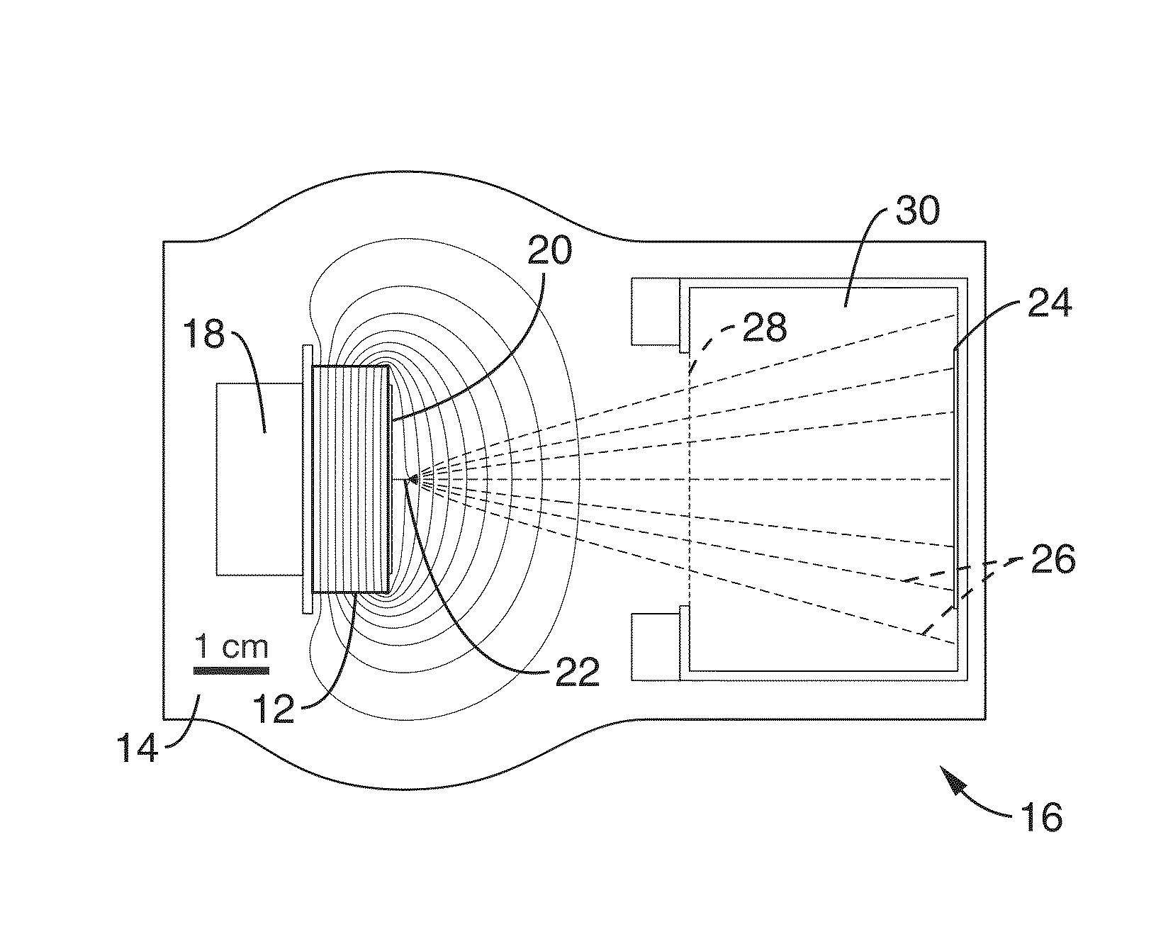
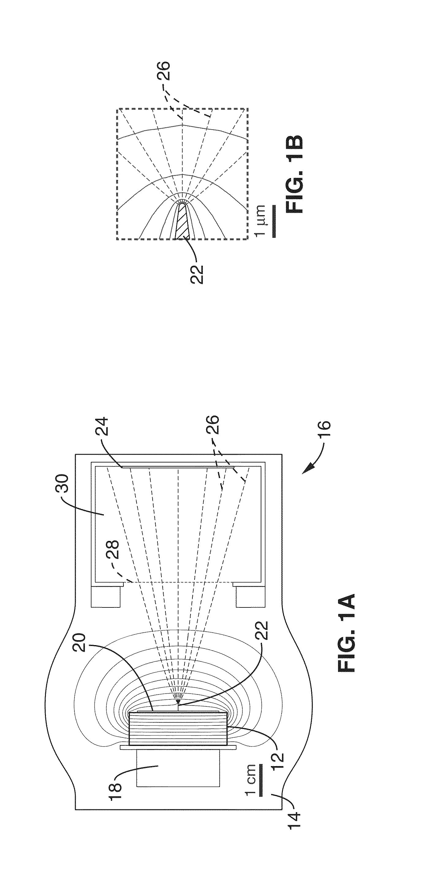
[0032]The vacuum chamber setup is shown in FIG. 1A. A cylindrical z-cut LiTaO3 crystal 12 (diameter, 3.0 cm; height, 1.0 cm) was mounted inside a chamber 14 with negative axis facing outward onto a hollow copper block 16. A heater 18 is located adjacent the crystal 12. On the exposed crystal face, we attached a copper disc 20 (diameter, 2.5 cm; height, 0.5 mm), allowing charge to flow to a tungsten probe 22 (shank diameter, 80 μm; tip radius, 100 nm; length, 2.3 mm) (FIG. 1B). The probe geometry was chosen so that the tip field was approximately 25 V nm−1 when the crystal face was charged to 80 kV. D2 pressure was set using a leak valve and monitored with a D2 compensated Pirani gauge. The target 24 was a molybdenum disc coated with ErD2.

[0033]FIG. 1A also shows calculated equipotentials and D+ trajectories 26 for a crystal charged to 100 kV; calculations were performed using finite-element methods. The grounded copper mesh 28 (85% open area, 19.8-mm wire) shields the Faraday cup 30...


PUM


Abstract

Gently heating a pyroelectric crystal in a deuterated atmosphere can generate fusion under desktop conditions. The electrostatic field of the crystal is used to generate and accelerate a deuteron beam (>100 keV and >4 nA), which, upon striking a deuterated target, produces a neutron flux over 400 times the background level. The presence of neutrons within the target is confirmed by pulse shape analysis and proton recoil spectroscopy. Several elements of the system may be modified, including the configuration of the crystal or crystals, the composition of the surrounding environment and the target, the use of multiple probe tips, and the composition of the probe tip.

Description

CROSS-REFERENCE TO RELATED APPLICATIONS[0001]This application priority from, and is a 35 U.S.C. §111(a) continuation of, co-pending PCT international application serial number PCT / US2006 / 000113, filed on Jan. 3, 2006, incorporated herein by reference in its entirety, which claims priority from U.S. provisional application Ser. No. 60 / 641,302, filed on Jan. 3, 2005, incorporated herein by reference in its entirety.STATEMENT REGARDING FEDERALLY SPONSORED RESEARCH OR DEVELOPMENT[0002]This invention was made with Government support under Grant No. DMR 0309886, awarded by the National Science Foundation and Grant Nos. N00014-03-1-07 and N00014-04-1-07, awarded by the Department of Defense. The Government has certain rights in this invention.NOTICE OF MATERIAL SUBJECT TO COPYRIGHT PROTECTION[0003]A portion of the material in this patent document is subject to copyright protection under the copyright laws of the United States and of other countries. The owner of the copyright rights has no...

Claims


Application Information

Patent Timeline
Patent Type & Authority Patents(United States)
IPC IPC(8): G21G4/02
CPCG21B3/006G21B3/00Y02E30/18Y02E30/10
Inventor NARANJO, BRIANGIMZEWSKI, JAMESPUTTERMAN, SETH
Owner RGT UNIV OF CALIFORNIA
Why Eureka
Try Eureka