Hydraulic drive system for sand and salt spreaders

a technology of hydraulic drive and spreader, which is applied in the direction of fluid coupling, centrifugal wheel fertiliser, instruments, etc., can solve the problems of relatively large pumps and achieve the effect of preventing pressure buildup in the system

Inactive Publication Date: 2013-03-19
PARKER HANNIFIN CORP
View PDF13 Cites 1 Cited by
  • Summary
  • Abstract
  • Description
  • Claims
  • Application Information

AI Technical Summary

Benefits of technology

[0007]The present invention provides a hydraulic drive system for a spreader used to distribute a road surface treatment material, such as sand or salt, across a road surface. The hydraulic drive system enables the use of pressure-compensated proportional control valves in series relationship with the auger and spinner motors, and thus eliminates the need for digital valving equipped with a bypass valve that prevents pressure buildup in the system when hydraulic fluid is not being supplied to the auger motor and / or spinner motor.
[0008]A preferred embodiment of the invention is characterized by the use of a lower cost and smaller displacement hydraulic pump that enables installation in the engine compartment of a vehicle so it can be driven by the engine's fan belt. This eliminates the need for and cost of a gasoline-powered auxiliary engine, as well as the associated noise, pollution, and maintenance requirements. The hydraulic pump need only be sized to provide hydraulic flow satisfying the larger of the flow requirements for the auger and spinner motors, rather than the sum of the requirements as in the case of parallel systems.
[0009]More particularly, a hydraulic system for operating the feed auger and spinner of a spreader includes first and second fluid motors for driving the feed auger and spinner. The fluid motors are connected in series with one another and first and second solenoid-operated pressure-compensated proportional control valves each including a pressure compensating spool. The first valve has an inlet configured to receive pressurized fluid from a source thereof such as an engine compartment mounted hydraulic pump, a regulated flow outlet connected to the inlet of the first fluid motor, and a bypass flow outlet, whereby operation of the valve controls the volume of flow of pressurized fluid supplied to the inlet of the first fluid motor via the regulated flow outlet with the balance of flow bypassing the first fluid motor. The second valve has an inlet connected to the outlet of the first fluid motor and the bypass flow outlet of the first valve, a regulated flow outlet connected to the inlet of the second fluid motor, and a bypass flow outlet, whereby operation of the second valve controls the volume of flow of pressurized fluid supplied to the inlet of the second fluid motor via the regulated flow outlet of the second valve with the balance of flow bypassing the second fluid motor. The system additionally includes first and second pressure-relieving restricted flow passages respectively connected between the regulated flow outlets and bypass flow outlets of the first and second valves for preventing pressure buildup at the regulated flow outlets of the first and second valves, thereby to assure proper operation of the compensator spools of the first and second valves.
[0011]In another preferred embodiment the restricted flow passage includes an orifice and a filter upstream of the orifice to prevent clogging of the orifice.

Problems solved by technology

These systems require relatively large pumps to supply adequate flow to the auger and spinner motors.

Method used


Image

  • Hydraulic drive system for sand and salt spreaders
  • Hydraulic drive system for sand and salt spreaders
  • Hydraulic drive system for sand and salt spreaders

Examples


Embodiment Construction

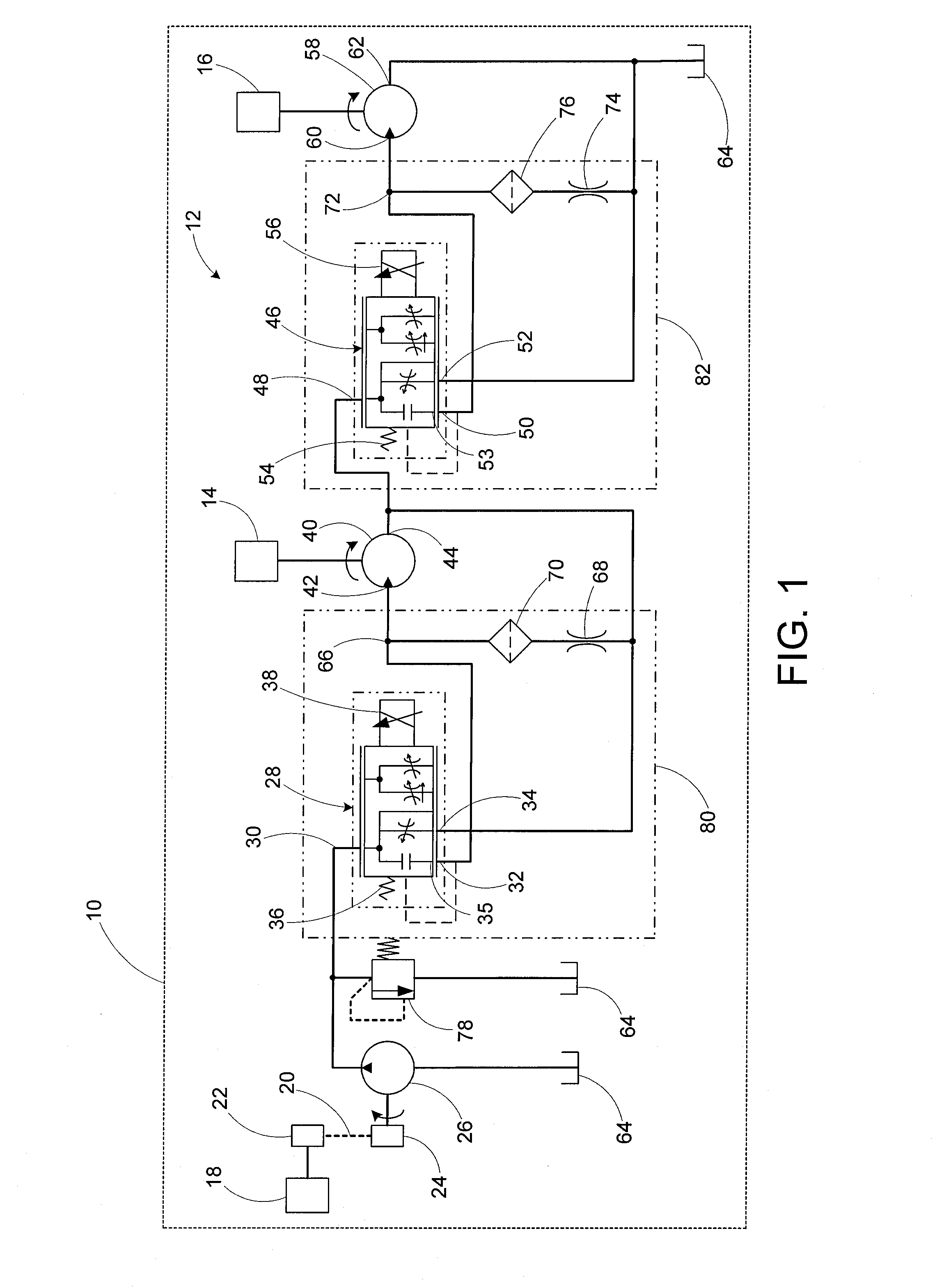
[0020]Referring now to the drawings in detail, and initially to FIG. 1, a snow-ice control vehicle 10 includes a hydraulic system 12 for operating a feed auger 14 and spinner 16 of a spreader carried by the snow-ice control vehicle. The hydraulic system can be installed in various snow-ice control vehicles, such as a pickup dump truck, and allows pressure-compensated proportional control valves in series relationship to be operated from the cab of the vehicle to provide independent control of the feed auger 14 and spinner 16. Accordingly, the system can be used in combination with the snow-ice control vehicle 10, having an engine 18, wherein the engine 18 has an engine-driven belt 20 that in conjunction with pulleys 22 and 24, couples the engine 18 to a pump 26, thereby allowing the pump 26 to be driven by the belt 20. The pump 26 may be configured for mounting in an engine compartment of the snow-ice control vehicle 10 to allow the pump 26 to be driven off the engine 18.

[0021]The p...


PUM


Abstract

A hydraulic drive system for a spreader used to distribute a road surface treatment material, such as sand or salt, across a road surface. The hydraulic drive system enables the use of pressure-compensated proportional control valves in series relationship with the auger and spinner motors, by the provision of small restricted flow passages across the outlets of the valves.

Description

RELATED APPLICATIONS[0001]This application claims the benefit of U.S. Provisional Application No. 61 / 243,508 filed Sep. 17, 2009, which is hereby incorporated herein by reference.FIELD OF INVENTION[0002]The present invention relates to hydraulic drive systems for spreaders used to distribute a road surface treatment material, such as sand or salt, across a road surface.BACKGROUND[0003]Hydraulic drive systems have been used to drive a feed auger and spinner of a spreader typically carried by a vehicle for spreading a road surface treatment material, such as sand or salt, across a road being traversed by the vehicle. The feed auger delivers the road surface treatment material from a supply thereof, such as a hopper, to the spinner which distributes the material across a road surface.[0004]Many of these systems are designed as self-contained units that can be mounted in the bed of a pickup dump truck. Pressurized hydraulic fluid is supplied by a hydraulic pump typically driven by a gas...

Claims


Application Information

Patent Timeline
Patent Type & Authority Patents(United States)
IPC IPC(8): A01C15/04
CPCE01H10/007F15B2211/4053F15B2211/50518F15B2211/7058F15B2211/7121F15B2211/7128
Inventor HARMS, LOUIS C.
Owner PARKER HANNIFIN CORP
Why Eureka
Try Eureka