
Integrated fuel cell assembly and method of making

a fuel cell and integrated technology, applied in the field of fuel cells, can solve the problems of mechanical weakness and difficulty in handling, difficulty in obtaining good positional alignment of trimmed uea profile features to the bpp features in the fuel cell stack assembly, and large voltage provided by a single cell unit for useful applications

Active Publication Date: 2013-03-19
GM GLOBAL TECH OPERATIONS LLC
View PDF5 Cites 41 Cited by
  • Summary
  • Abstract
  • Description
  • Claims
  • Application Information

AI Technical Summary

Benefits of technology

The present invention provides an integrated fuel cell assembly and a method of making it. The integrated fuel cell assembly includes a polymer membrane, anode and cathode electrodes on opposite sides of the membrane, gas diffusion media with a microporous layer and gas diffusion layer, a subgasket with a layer of thermally activated adhesive, and a bipolar plate sealed to the subgasket. The method involves placing the integrated fuel cell assembly between two bipolar plates, heating the thermally activated adhesive to seal them, and stacking and compressing the assemblies. This invention allows for more efficient and compact fuel cell stacks.

Problems solved by technology

The voltage provided by a single cell unit is typically too small for useful applications.
Some current UEAs are made with thin film subgaskets, in the range of 1 to 2 mil thick, which are mechanically weak and can be difficult to handle.
When the UEA with a thin subgasket is assembled into a fuel cell stack as a discrete component it can be difficult to obtain good positional alignment of the trimmed UEA profile features to the BPP features in the fuel cell stack assembly.
The subgasket material of the UEA needs to be sealed between adjacent plate assemblies of the fuel cell as the subgasket film materials do not provide adequate sealing integrity to the plate materials on their own.
PSAs present on these overhanging subgaskets can pose additional stack assembly issues as the adhesives are exposed and active in these areas where adhesive function is not necessarily desired.

Method used


Image

  • Integrated fuel cell assembly and method of making
  • Integrated fuel cell assembly and method of making
  • Integrated fuel cell assembly and method of making

Examples


Embodiment Construction

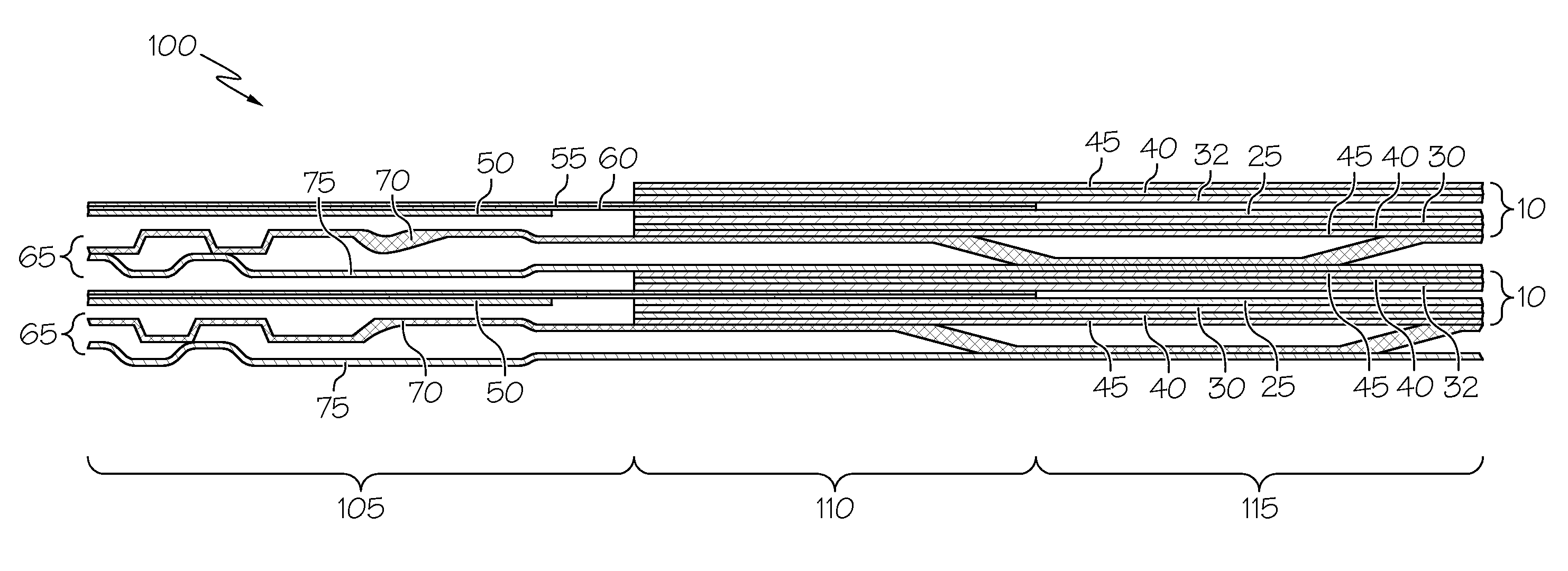
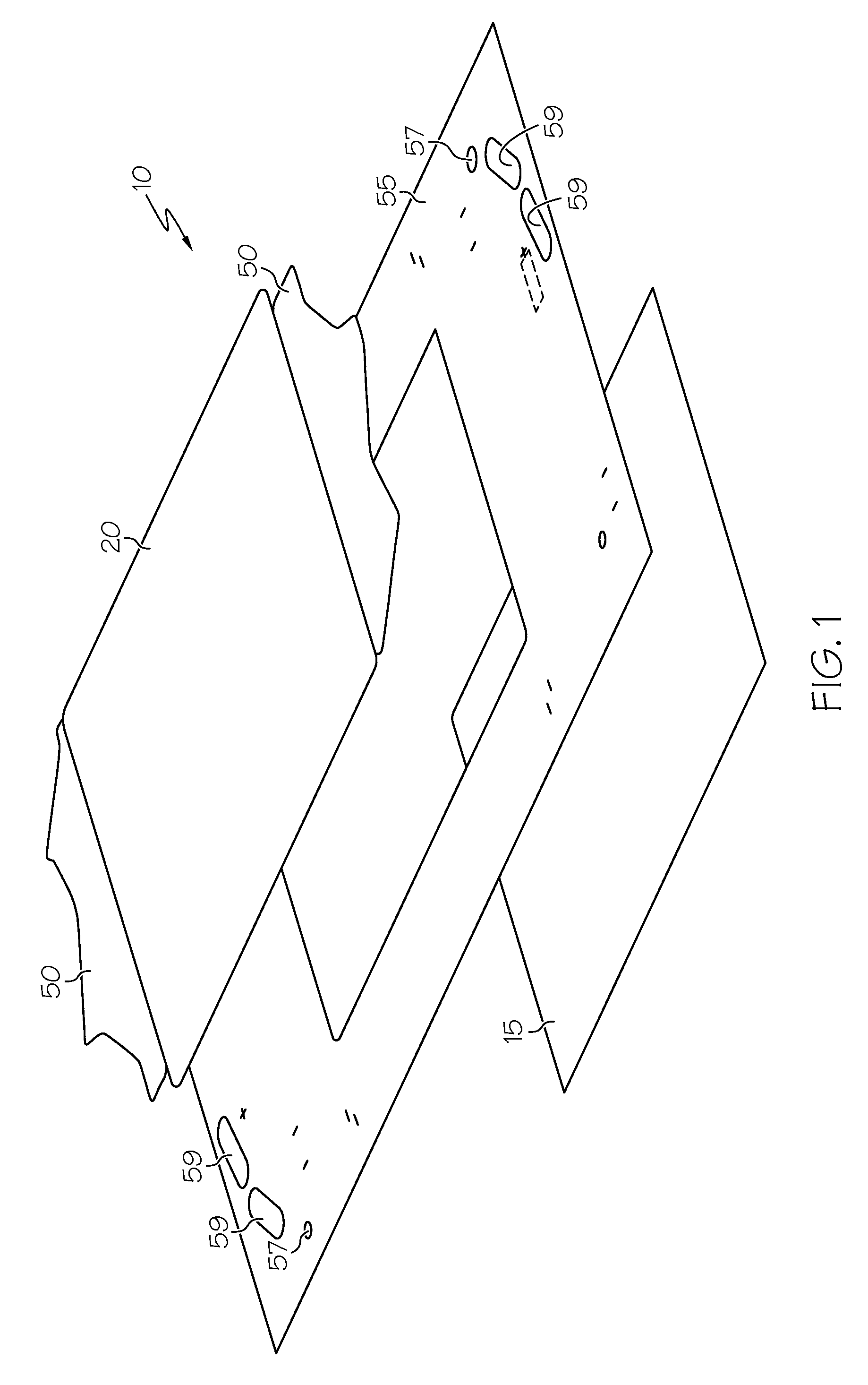
[0014]FIGS. 1, 2A and 2B illustrate a unitized electrode assembly (UEA) 10. The UEA 10 includes an anode 15 and a cathode 20 on opposite sides of a proton exchange membrane (PEM) 25. In this embodiment, the anode 15 and cathode 20 are catalyst coated diffusion media (CCDM) CCDM, with a cathode electrode layer 30 and an anode electrode layer 32 on the gas diffusion media (GDM) GDM 35, which includes a microporous layer (MPL) 40 and gas diffusion layer 45. The cathode electrode layer 30 and the anode electrode layer 32 are on the MPL 40. However, the catalyst coated membrane (CCM) (in which the electrode layer is on the PEM) could also be used, if desired.

[0015]There is a subgasket 55 between the anode 15 and cathode 20. The subgasket 55 surrounds the perimeter of the active area of the anode 15 and cathode 20 (similar to a picture frame). The subgasket can be made of any polymer film that meets fuel cell requirements (e.g., having appropriate mechanical properties based on operating ...


PUM

PropertyMeasurementUnit
pressuresaaaaaaaaaa
pressuresaaaaaaaaaa
thickaaaaaaaaaa

Abstract

An integrated fuel cell assembly is described. The integrated fuel cell assembly includes a polymer membrane; an anode electrode and a cathode electrode on opposite sides of the polymer membrane; a pair of gas diffusion media on opposite sides of the polymer membrane, the gas diffusion media comprising a microporous layer and a gas diffusion layer, the anode electrode and the cathode electrode positioned between the polymer membrane and the pair of gas diffusion media; a subgasket positioned around a perimeter of one of the gas diffusion media, the subgasket defining an active area inside the perimeter, the subgasket having a layer of thermally activated adhesive thereon; and a bipolar plate sealed to the subgasket by the layer of thermally activated adhesive. Methods of making the integrated fuel cell assembly and assembling fuel cell stacks are also described.

Description

FIELD OF THE INVENTION[0001]The present invention relates generally to fuel cells, and more particularly to integrated fuel cell assemblies, and to methods of making them.BACKGROUND OF THE INVENTION[0002]Electrochemical conversion cells, commonly referred to as fuel cells, produce electrical energy by processing first and second reactants, e.g., through oxidation and reduction of hydrogen and oxygen. By way of illustration and not limitation, a typical polymer electrolyte fuel cell comprises a polymer membrane (e.g., a proton exchange membrane (PEM)) that is positioned between a pair of catalyst layers and a pair of gas diffusion media (GDM). The GDM typically includes a gas diffusion layer and a microporous layer (MPL). The cathode electrode layers can be part of the PEM (catalyst coated membrane (CCM)) or as a layer on the DM (catalyst coated diffusion media (CCDM)). A cathode plate and an anode plate (or bipolar plates BPP) are positioned at the outermost sides adjacent the gas d...

Claims


Application Information

Patent Timeline
Patent Type & Authority Patents(United States)
IPC IPC(8): H01M2/08H01M4/02H01M8/10
CPCH01M8/0273H01M8/0284H01M8/0286H01M8/241H01M8/1004Y10T29/49114H01M2008/1095Y02E60/521H01M8/242Y02E60/50Y02P70/50
Inventor MILLER, DANIEL P.BEUTEL, MATTHEW J.BHARGAVA, SUMEETREICH, COURTNEY E.
Owner GM GLOBAL TECH OPERATIONS LLC
Learn More