High specific force capacity thrust magnetic bearing and method of making

a magnetic bearing and high specific force technology, applied in the direction of magnetic circuit rotating parts, magnetic circuit shape/form/construction, mechanical equipment, etc., can solve the problems of high rotational speed failure of disk material, insufficient volume, and inoptimal configuration described in prior art, so as to reduce the amount of time required

Active Publication Date: 2013-03-19
MAINSTREAM ENG
View PDF6 Cites 4 Cited by
  • Summary
  • Abstract
  • Description
  • Claims
  • Application Information

AI Technical Summary

Benefits of technology

[0021]To provide a general parameterization of thrust bearing geometry that captures the features of an optimized stator coil and magnetic material so as to provide nearly uniform flux saturation, resulting in maximum force capacity and therefore minimum size, minimum weight, and maximum efficiency for a given target force capacity
[0022]To provide the methods necessary for selecting parameters for the configuration geometry, including the process and equations that will reduce the amount of time necessary to converge upon the best solution.

Problems solved by technology

In general, the configurations described in prior art are not optimal due to flux leakage and inefficient use of stator magnetic material.
Since not all of the stator material is fully saturated, some volume is effectively being wasted.
The problem is compounded by the fact that some of the thrust bearing volume could be utilized by making the coil larger, which would in turn provide more available capacity for a given current density.
In some applications, such a thrust disk would lead to failure of the disk material at high rotational speeds due to excessive stress at the thrust disk hub.
Therefore, it can only be used when the rotational speed is low.
The major problem with these designs is that a specific part of the stator saturates before the rest of the stator.
This results in a sub-optimal design in which not all of the stator material is used efficiently, and hence the force capacity is not maximized.
Even if the dimensions of the rectangular region are optimized, the problem is not rectified.
It is an inherent property of this parameterization that results in an inefficient thrust actuator design.

Method used


Image

  • High specific force capacity thrust magnetic bearing and method of making
  • High specific force capacity thrust magnetic bearing and method of making
  • High specific force capacity thrust magnetic bearing and method of making

Examples


Embodiment Construction

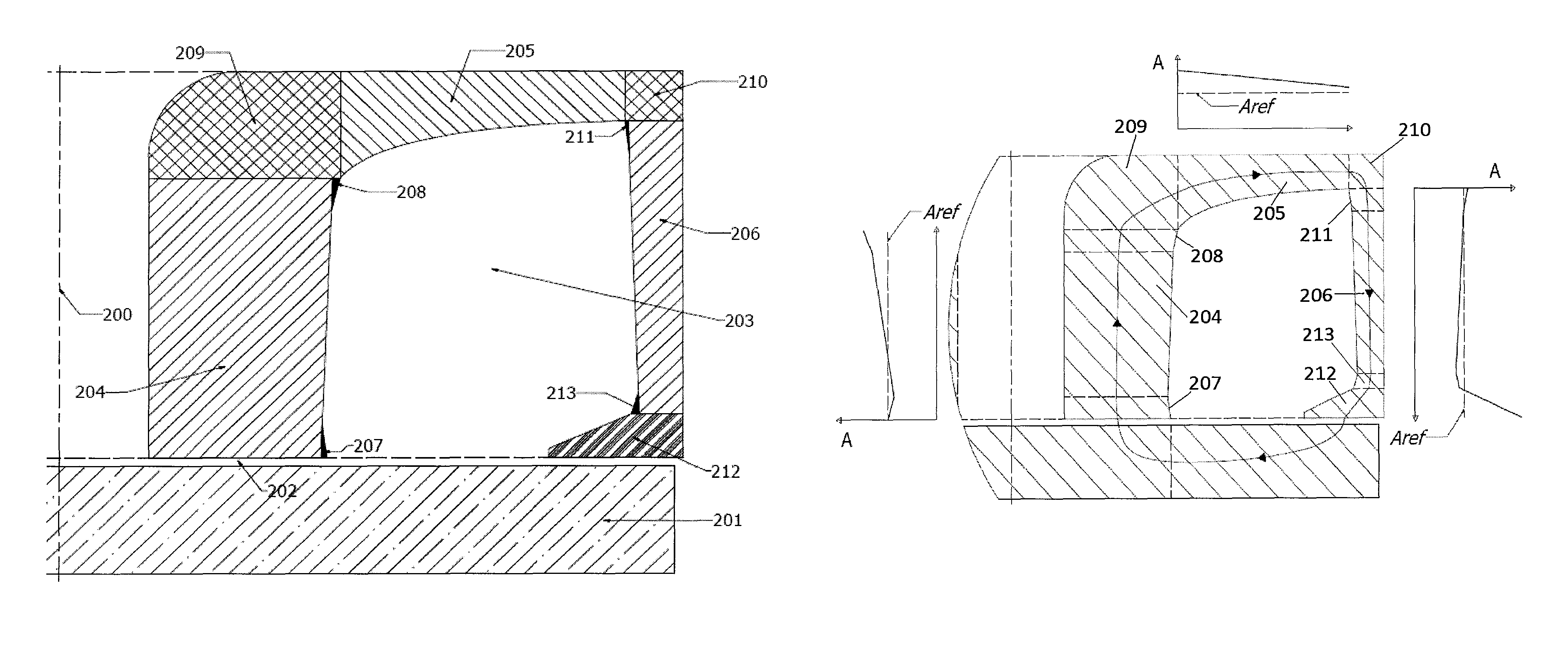
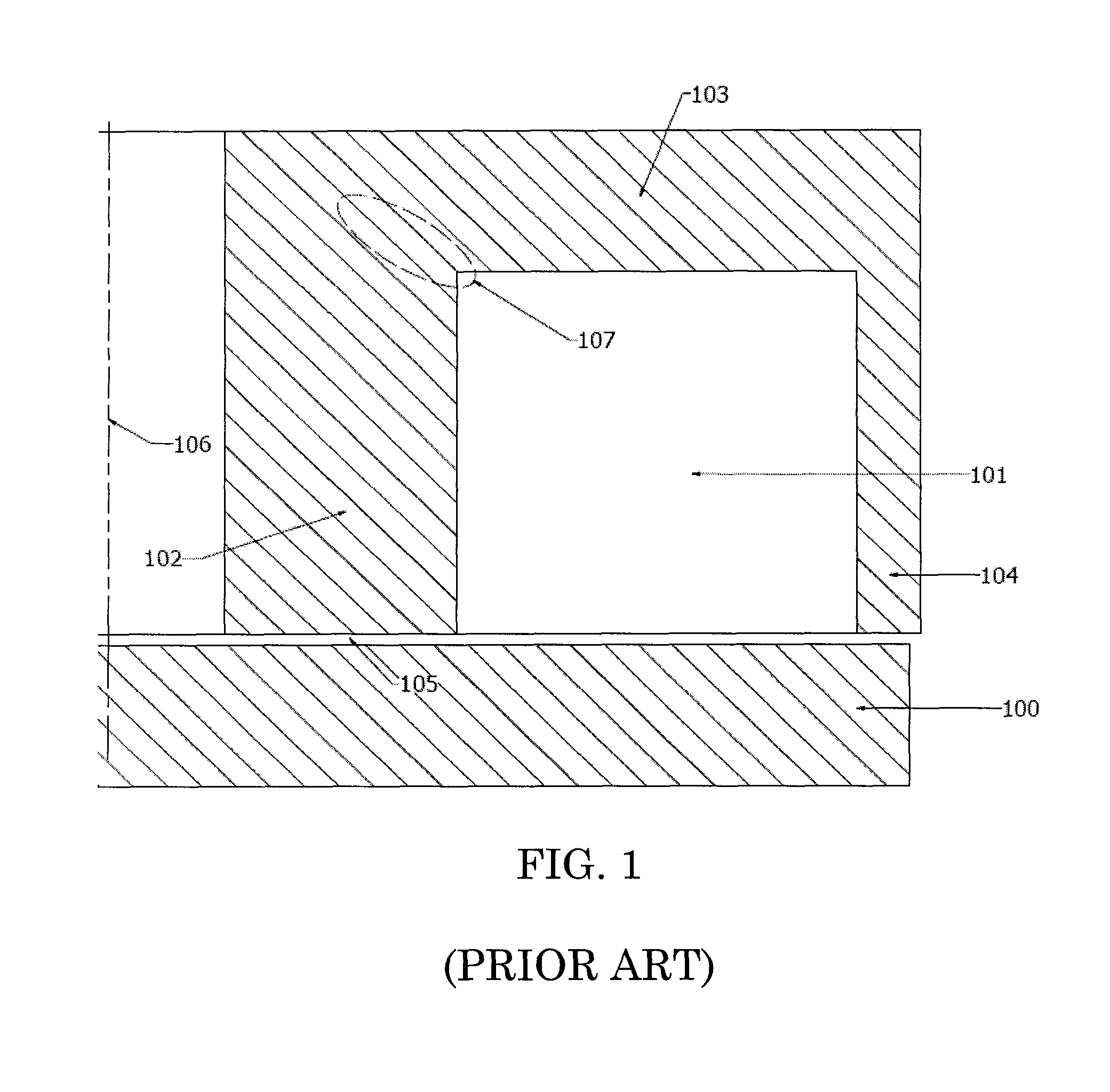
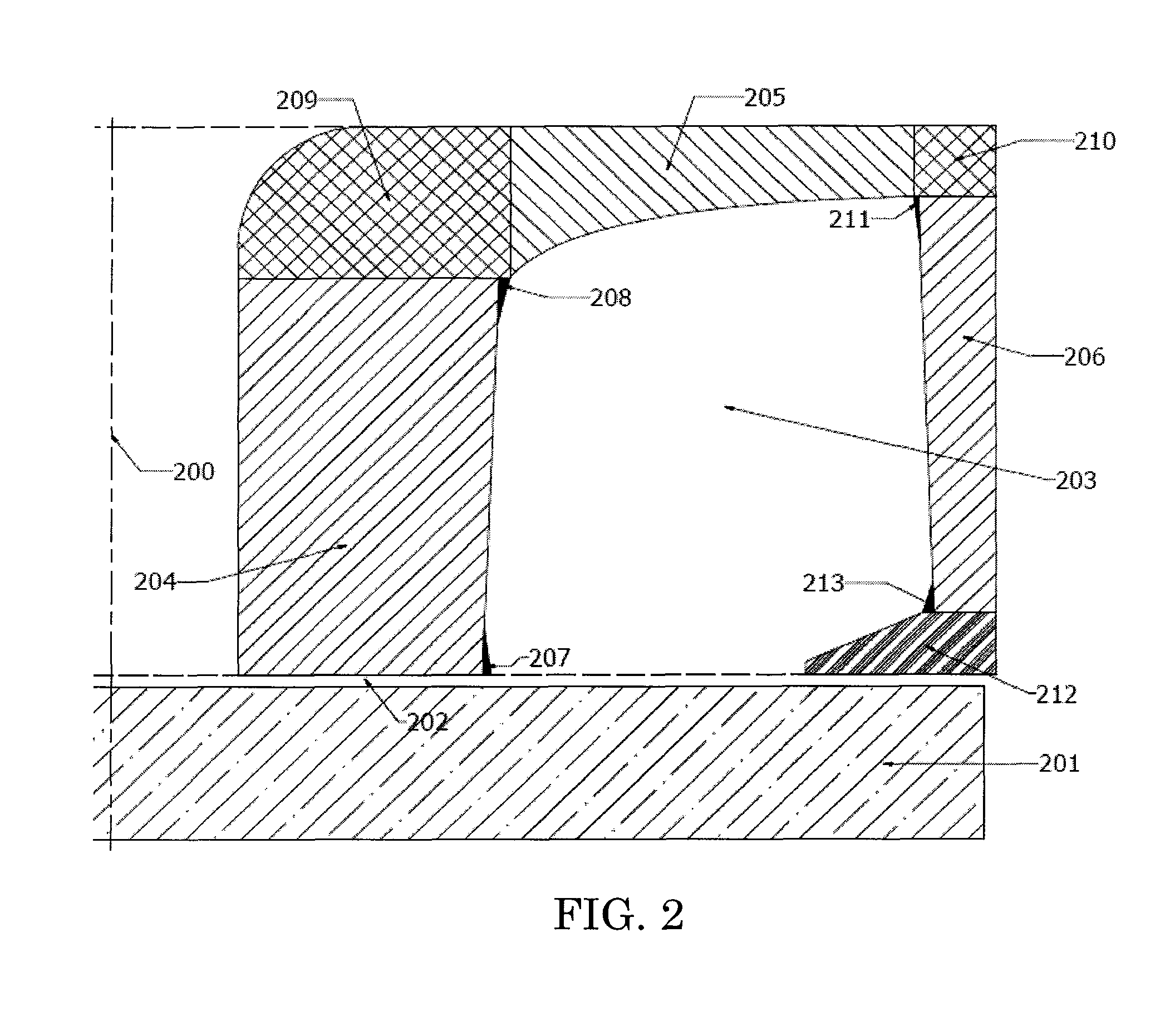
[0029]FIG. 2 shows a cross-sectional geometry that is a substantially improvement in efficiency over the prior art. In order to compare the conventional configuration in FIG. 1, the axis of revolution 200, thrust disk 201, air gap 202 in FIG. 2, and all exterior stator dimensions are the same as in FIG. 1. Unlike the prior art, however, the coil cavity 203 is not rectangular, but rather forms a loop that creates a highly variable cross-sectional area normal to the flux path. The stator still has three major regions as shown in FIG. 2, namely inner pole 204, back face 205, and outer pole 206. FIG. 3 shows how the cross-sectional area changes in these three regions, with area plotted versus distance and the area of the inner pole at the air gap labeled as Aref.

[0030]The flux path is shown in FIG. 3 as a closed loop with arrows indicating direction. Starting from the inner pole air gap and going clockwise, the cross-sectional area decreases from Aref along the gap face inner pole exten...


PUM


Abstract

A specific force capacity thrust bearing and a method for producing such a design for a particular application are disclosed. The magnetic flux density in the stator material is maximized by varying cross-sectional area normal to the flux path. After a set of initial parameters are chosen, the design can be improved upon by changing the design variables and then verifying the force capacity using a finite element program. By linking the finite element program to a model of the geometry and using some basic algorithms, it is possible to automatically iterate until an optimal design is reached. The resulting design has a much higher force capacity than designs typical of the prior art.

Description

BACKGROUND OF THE INVENTION[0001]1. Field of Art[0002]This invention relates generally to electromagnetic actuators, and especially to thrust actuators for magnetic bearing systems. Improvements in thrust bearing specific force capacity allow for smaller, lighter stators and enable operation at higher speeds.[0003]2. Description of Related Art[0004]Active magnetic bearing (AMB) systems usually have two opposing thrust bearings, one on either side of a thrust disk that is mounted on the shaft. By controlling the current in each of the bearings, the net force on the thrust disk can be controlled in either direction to stabilize the shaft assembly in the axial direction against both static and dynamic forces.[0005]Thrust bearings for AMB systems generally consist of three major components. The stator, which is a stationary cylindrical component made of magnetic material, provides a flux path and houses the coil. The coil, which is a toroidal winding of electrically conductive wire, pro...

Claims


Application Information

Patent Timeline
Patent Type & Authority Patents(United States)
IPC IPC(8): H02K7/09
CPCF16C32/0461F16C32/0476
Inventor LASKO, THOMAS M.MASON, DANIEL K.
Owner MAINSTREAM ENG
Why Eureka
Try Eureka