

Stopper device for grinding stone cover of grinder
a technology of stopper device and grinder, which is applied in the direction of metal-working equipment, portable grinding machines, manufacturing tools, etc., can solve the problems of affecting usability, affecting the efficiency of operation, and affecting the function of dust scattering prevention, so as to prevent dust from scattering, improve operation efficiency, and effectively prevent the effect of dust scattering towards the user
- Summary
- Abstract
- Description
- Claims
- Application Information
AI Technical Summary
Benefits of technology
Problems solved by technology
Method used
Image

Examples
first embodiment
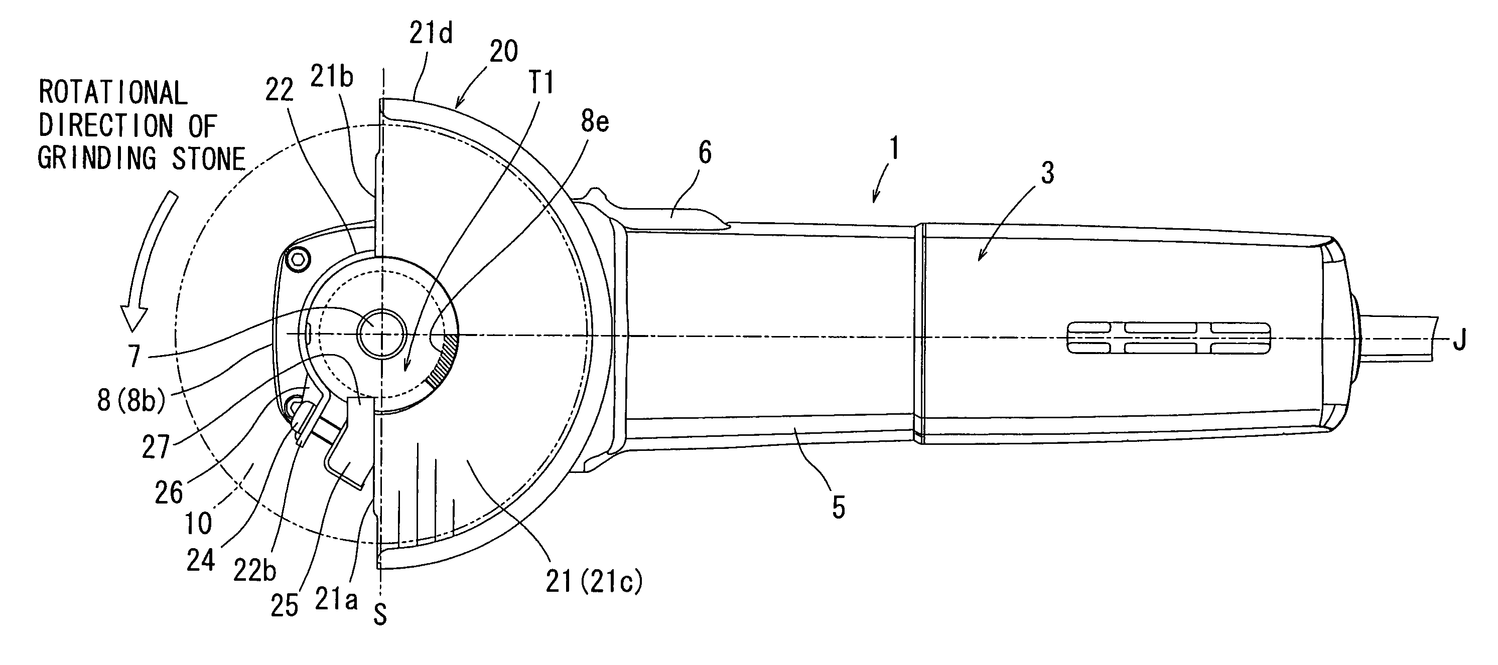
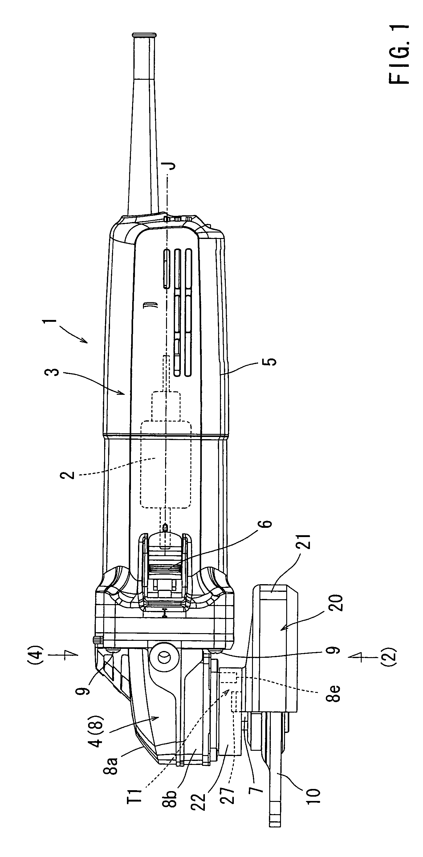
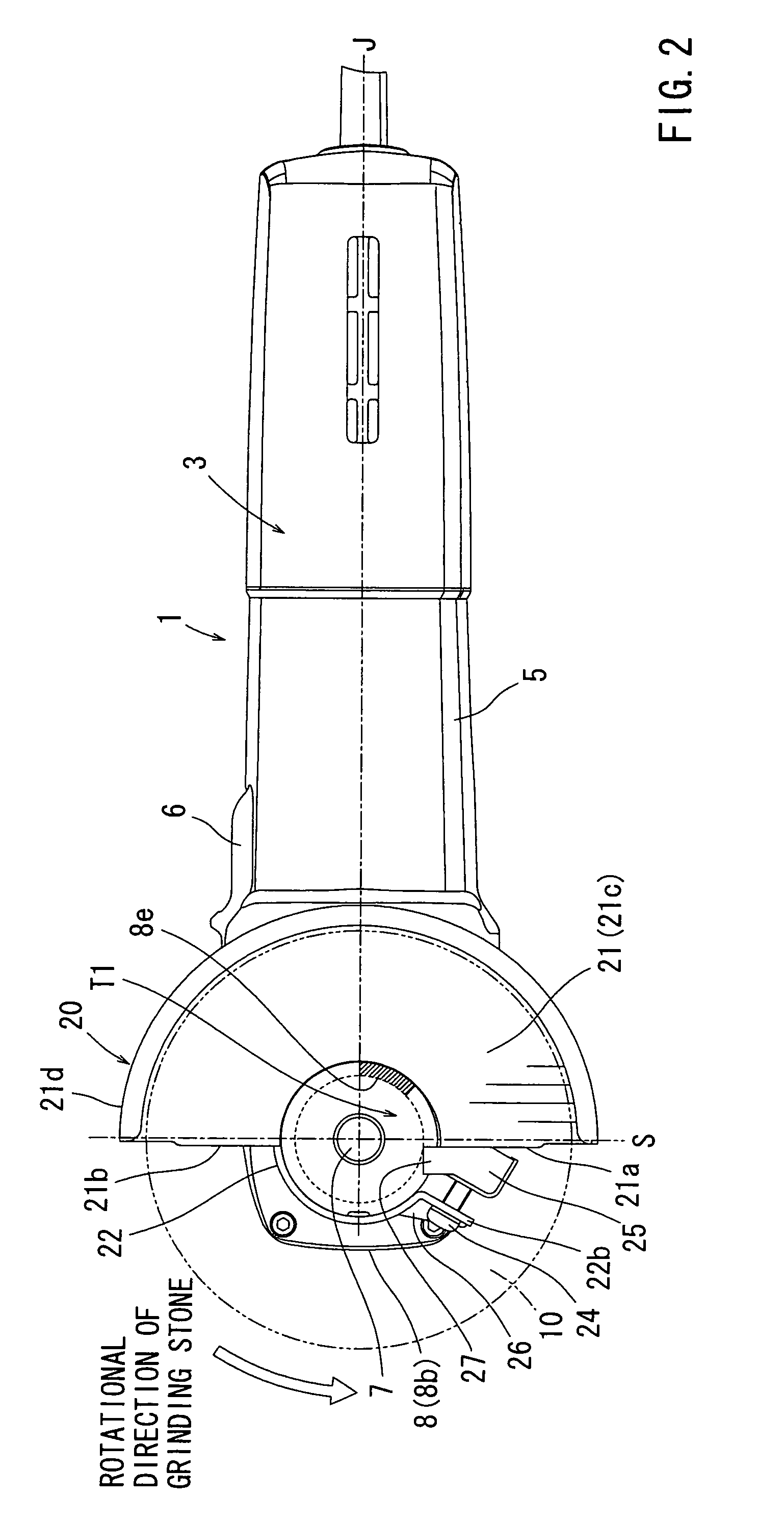
[0026]Next, embodiments of the present invention will be described with reference to FIGS. 1 to 11. FIG. 1 shows a grinder 1 having a stopper device T1 according to a A fundamental construction of the grinder 1 needs no particular change for this embodiment, however, it will be briefly described below. A left side in FIG. 1 will be referred to as a front side of the grinder 1 and a right side will be referred to as a rear side.
[0027]The grinder 1 includes a main body portion 3 and a speed reduction gear portion 4. The main body portion 3 includes a main body housing 5 having a substantially cylindrical configuration. An electric motor 2 serving as a power source is received within the main body housing 5. The main body housing 5 and the main body portion 3 also serve as a grip portion having such a thickness that allows a user to easily hold it. The user may be positioned on a rear side of the main body portion 3 to hold the main body portion 3. A main switch 6 of a slide operation...
second embodiment
[0049]The stopper abutting portion 31 is provided in a state of entering the movement path of both fixing screw tightening portions 22a, 22b in accordance with the rotation of the grinding stone cover 30 in the rotational direction of the grinding stone. Therefore, when the position of the shielded range for the grinding stone 10 is adjusted by rotating the grinding stone cover 30 in the rotational direction of the grinding stone, further rotation is prevented as the leading end portion of the fixing screw tightening portion 22a or the fixing screw 24 abuts the stopper abutting portion 31. In the second embodiment as well, the position adjustable range of the grinding stone cover 30 in the rotational direction of the grinding stone is restricted to the opening angle θ that is 60 degrees at the maximum from the reference position S.
[0050]As described above, according to the stopper device T2 of the second embodiment, the same operation and effects can be obtained as of the first embo...
third embodiment
[0056]Also, the bent portion 40a is provided on an upper portion of the stopper fitting 40 of the The bent portion 40a extends along over the upper side of the stopper main body 31a. With the bent portion 40a, the upward displacement of the stopper projection 41 abutted to the stopper main portion 31a is restricted so that its removal is prevented, and therefore, the position adjustable range restricting function of the stopper device T3 can be reliably exercised because the abutting condition can be reliably maintained.
[0057]The additional modifications may be respectively made to the above-described third embodiment. For example, as shown in FIG. 11, the opening angle θ of the grinding stone cover 20 can be reliably restricted by providing a stopper restricting protrusion 28 in a position adjacent to the stopper projection 27 of the first embodiment. Similar to the removal preventing protrusion 22d, the stopper restricting protrusion 28 is provided on the inner circumferential su...
PUM
 Abstract
Description
Claims
Application Information