Solar reflector, collecting window and heat storage

a solar reflector and window technology, applied in the safety of solar heat collectors, solar heat storage, lighting and heating apparatus, etc., can solve the problems of infrared heat going, leaking heat through glass, and waste of heat, so as to reduce heat loss and reduce heat loss

Inactive Publication Date: 2013-04-02
KLINKMON PAUL M
View PDF19 Cites 12 Cited by
  • Summary
  • Abstract
  • Description
  • Claims
  • Application Information

AI Technical Summary

Benefits of technology

[0013]Solar space heating is a blend of gathering quantities of sunlight and heat, storing heat and losing as little heat as possible. A reflector and target window combination concentrates a great deal of sunlight into a building cheaply. Later heat loss is minimized by having relatively tiny target windows. Great amounts of heat are economically stored in the tons of ground several feet underneath the center of the greenhouse. This storage solution keeps the greenhouse's indoor temperature moderately steady over the long term.

Problems solved by technology

Greenhouses are notorious wasters of heat in cold climates, which is expensive to the point where most winter produce is trucked in from tropical regions.
Most greenhouses suffer the fundamental problem that if light can come into a window in the daytime, infrared heat can go out the same window at night and during cloudy weeks in winter.
This design often leaks heat through the glass, both convective heat and radiated heat.
Also, many glass windows leak air around their edges.
While having two layers of plastic reduces heat losses and eliminates air leaks, heat losses at night and on cloudy days are still substantial.
Also, the vinyl sheets decay after about four years and become toxic waste.
This device does reduce heat losses at night, but requires equipment to blow the Styrofoam pellets in and out.
The problem of gathering sparse sunlight on windy, mostly cloudy days with in-and-out sun and clouds remains unsolved.
Furthermore, the Fresnel lens is in a vulnerable wind position, the windows are placed facing the sky so that the window might leak or be covered with dry leaves or other flammable materials, and the lens might become snow-covered.
However, this particular design has snow shoveling and ice collection problems or can be covered with leaves, and the reflector could still be somewhat shaded by taller trees and buildings to the south.
The collector pipe is up in the air, creating insulation costs for the collector pipe.
Any heat leaking through the collector pipe's insulation is lost.
If the collector's pump should ever fail then the collector might overheat and be damaged.

Method used


Image

  • Solar reflector, collecting window and heat storage
  • Solar reflector, collecting window and heat storage
  • Solar reflector, collecting window and heat storage

Examples


Embodiment Construction

[0045]In the invention's primary embodiment,

[0046]Note that the approximate directions north, south, east and west will be used in this document to describe applications in the temperate zone of the northern hemisphere. In the northern hemisphere the winter solstice occurs on or near December 21 of each year. Such directions would be reversed in the temperate zone of the southern hemisphere. In nearly equatorial sites such as, say, for example, at high altitudes, the south and north directions may be either reversed or maintained as is. At or near the earth's poles the direction of “north” may be nearly arbitrary for siting purposes.

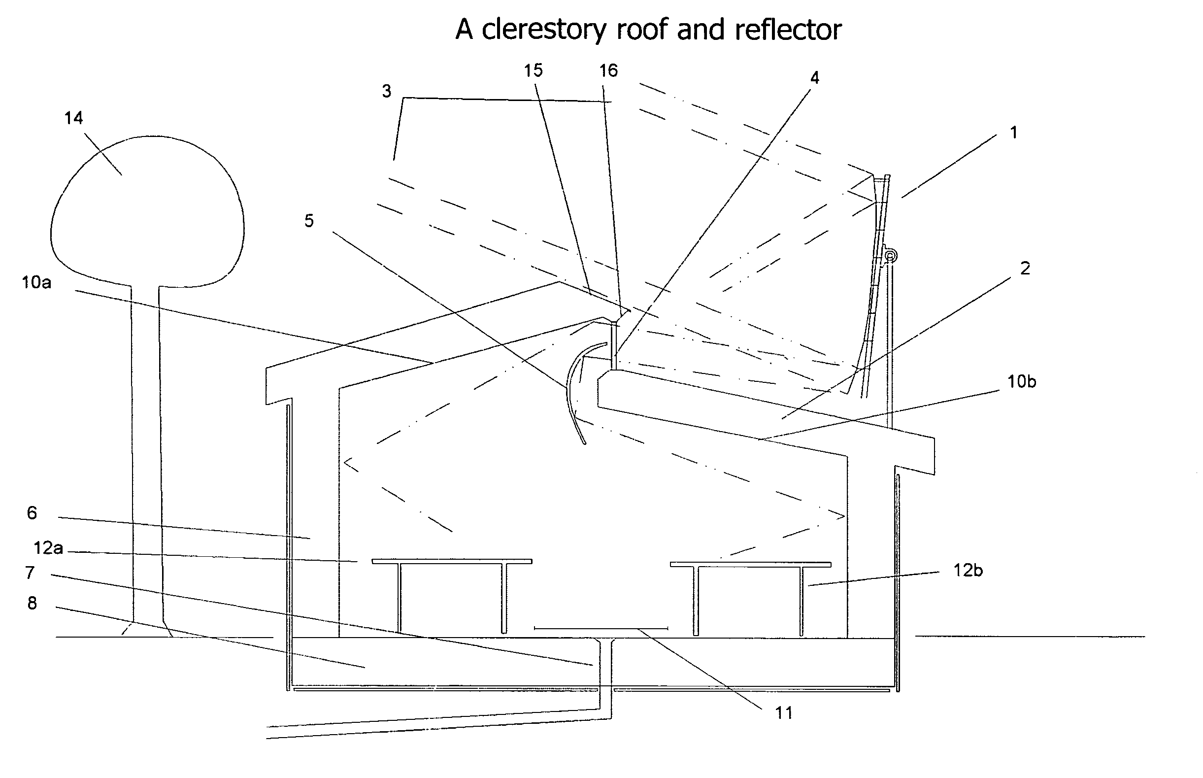
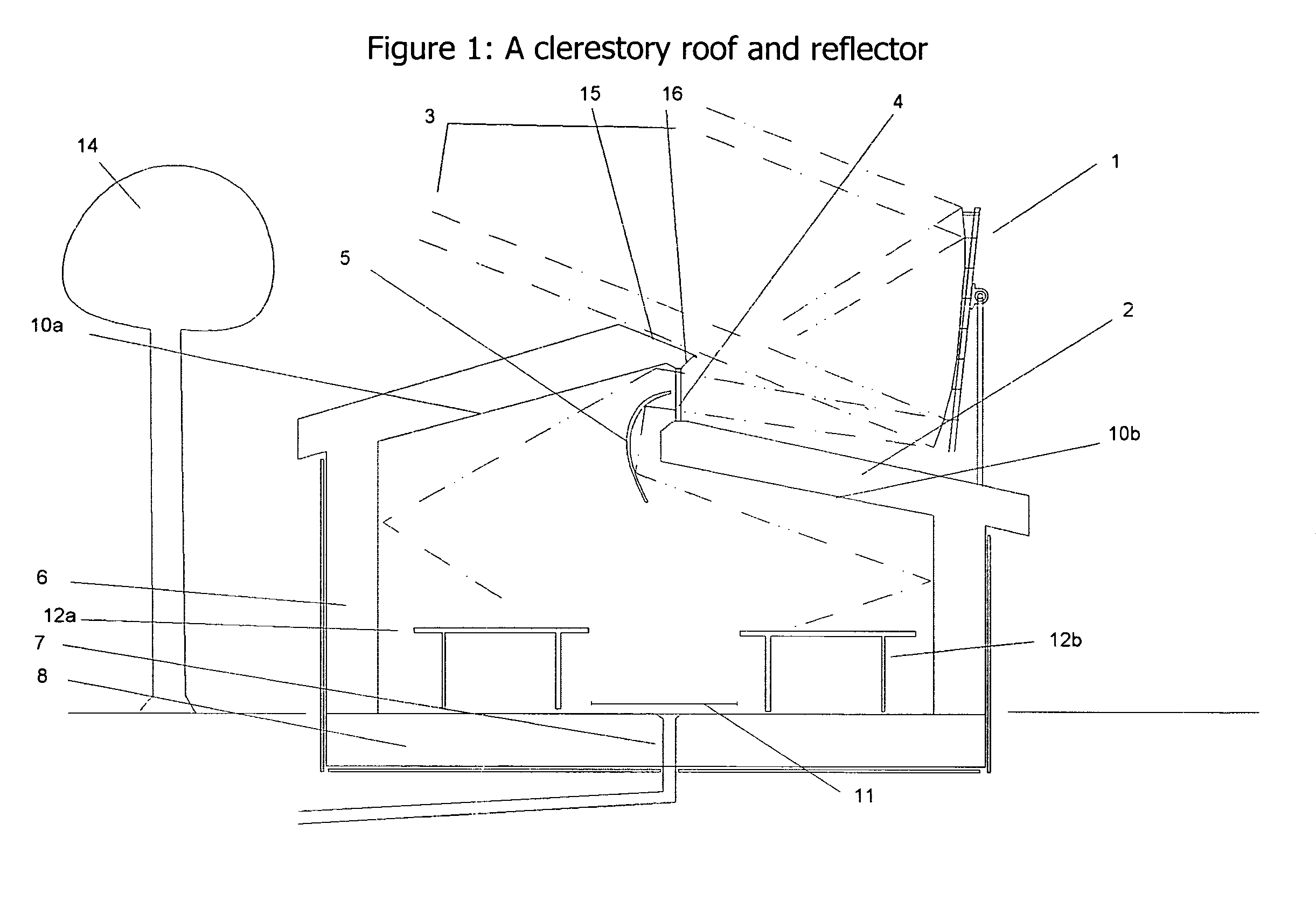
[0047]In the embodiment shown in FIG. 1, a reflective linear trough (1) on a building roof, such as a greenhouse roof (2), concentrates sunlight (3) from any spot on the sun's daily arc from east through south to west, through a horizontally long target window (4), which may be, but doesn't have to be, a long series of smaller target windows in a line, i...


PUM


Abstract

A linear trough concentrates sunlight through a long target window in a greenhouse's roof or north wall. Heat is stored in a geothermal heat bank below the greenhouse's center, where a thermal skirt around the greenhouse reduces heat loss.

Description

CLAIM OF PRIORITY[0001]This application for patent claims priority from provisional patent application 60 / 944,902 filed by the inventor's agent on Jun. 19, 2007.REFERENCES CITED[0002]U.S. PatentsPat. No.TitleIssue date4,198,953Solar illuminated energy Apr. 22, 1980conserving greenhouse4,257,400Combined roof and solar heat structureMar. 24, 19814,111,360Solar energy concentrating and Sep. 5, 1978collecting arrangement and methodFIELD OF THE INVENTION[0003]This invention relates generally to Solar Heat Collectors, and, more particularly, to reflecting and concentrating sunlight and storing heat.BACKGROUND OF THE INVENTION[0004]Greenhouses are notorious wasters of heat in cold climates, which is expensive to the point where most winter produce is trucked in from tropical regions. Most greenhouses suffer the fundamental problem that if light can come into a window in the daytime, infrared heat can go out the same window at night and during cloudy weeks in winter.[0005]Standard glass gre...

Claims


Application Information

Patent Timeline
Patent Type & Authority Patents(United States)
IPC IPC(8): F24J2/46
CPCH01L31/052F24J2/14F24J2/16F24J2/34F24J2/4638H02S40/22H01L31/0488H01L31/0521Y02E10/45Y02B10/12Y02E10/52Y02B10/20F24S23/74F24S23/77F24S40/85F24S60/00H02S40/425Y02B10/10Y02E10/40
Inventor KLINKMAN, PAUL M.
Owner KLINKMON PAUL M
Why Eureka
Try Eureka