Laser scanning assembly having an improved scan angle-multiplication factor

a laser scanning and multiplication factor technology, applied in the field of optical scanning devices, can solve the problems of loss of light collection ability, difficult to avoid, and the configuration of laser scanning does not amplify the scan angle multiplication factor of the pair of rotating mirrors beyond. achieve the effect of uniform light collection

Inactive Publication Date: 2013-04-02
METROLOGIC INSTR INC
View PDF27 Cites 788 Cited by
  • Summary
  • Abstract
  • Description
  • Claims
  • Application Information

AI Technical Summary

Benefits of technology

[0013]Another object is to provide a rotatable laser scanning assembly allowing the scan angle multiplication factor of the rotating mirrors to be as high as three, while providing very uniform beam motion through a full 360 degrees around the laser scanning assembly.
[0015]Another object is to provide a rotatable laser scanning assembly allowing the laser scanning assembly to be physically larger than any individual cluster mirror, and consequently, allowing the light collection to be nearly uniform with scan angle, dropping less than 4% for a 30 degree scan sweep.

Problems solved by technology

However, a disadvantage of the polygon scanning element employed in such prior art scanning systems is that the achievable sweeping scan angle of a laser beam reflected off of such a scanning polygon can be no greater than two times the angle of rotation, and is usually less than two times. Also, in order to approach the limiting factor of two, the incident laser beam as well as the normal vectors to the mirror surfaces must be nearly perpendicular to the rotation axis.
Additionally, traditional rotating polygons, with a scan multiplication factor near two, experience a loss of light collecting ability as they rotate away from a point of symmetry due to the narrowing of the apparent width of the mirror as it rotates.
This happens if the polygon mirror is the limiting light-collection aperture of the system, which can be difficult to avoid in a traditional system design.
And while U.S. Pat. No. 5,177,347 discloses a polygon-based laser scanning system, in which a pair of rotating mirrors are used with a stationary cluster of mirrors, this laser scanning configuration does not amplify the scan angle multiplication factor of the pair of rotating mirrors beyond two, nor does it provide circular coverage.

Method used


Image

  • Laser scanning assembly having an improved scan angle-multiplication factor
  • Laser scanning assembly having an improved scan angle-multiplication factor
  • Laser scanning assembly having an improved scan angle-multiplication factor

Examples


Embodiment Construction

[0025]Referring to the figures in the accompanying drawings, the various illustrative embodiments of the present invention will be described in greater detail, wherein like elements will be indicated using like reference numerals.

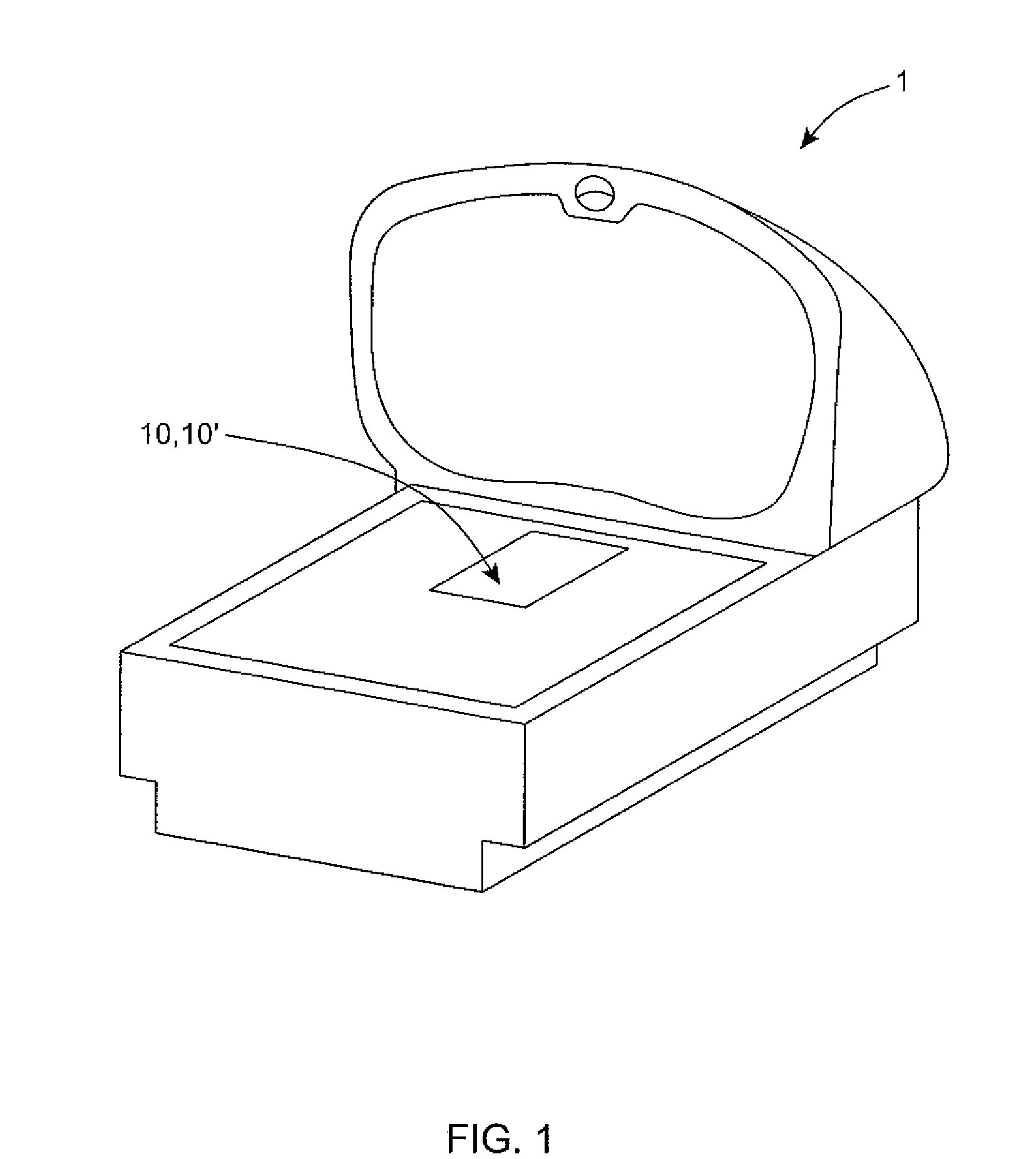
[0026]In general, the laser scanning assembly of the present disclosure can be embodied in diverse kinds of optical scanning systems. For purposes of illustration, FIG. 1 shows the laser scanning assembly embodied in a point of sale (POS) laser scanning system 1. It is understood, however, that the laser scanning assembly 10, 10′ can be installed in other types of laser scanning systems, including hand-supportable, POS-projection and industrial type laser scanning systems.

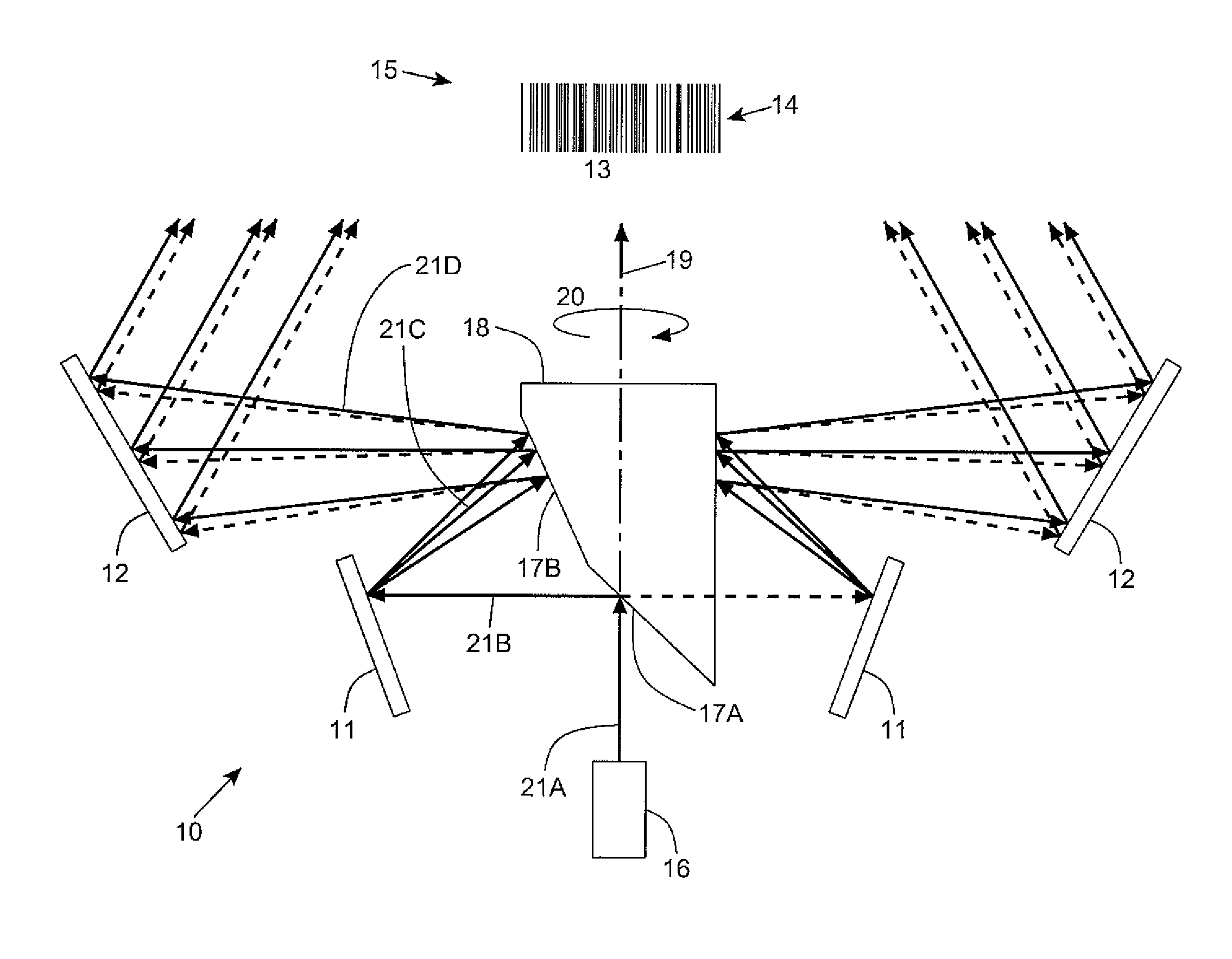
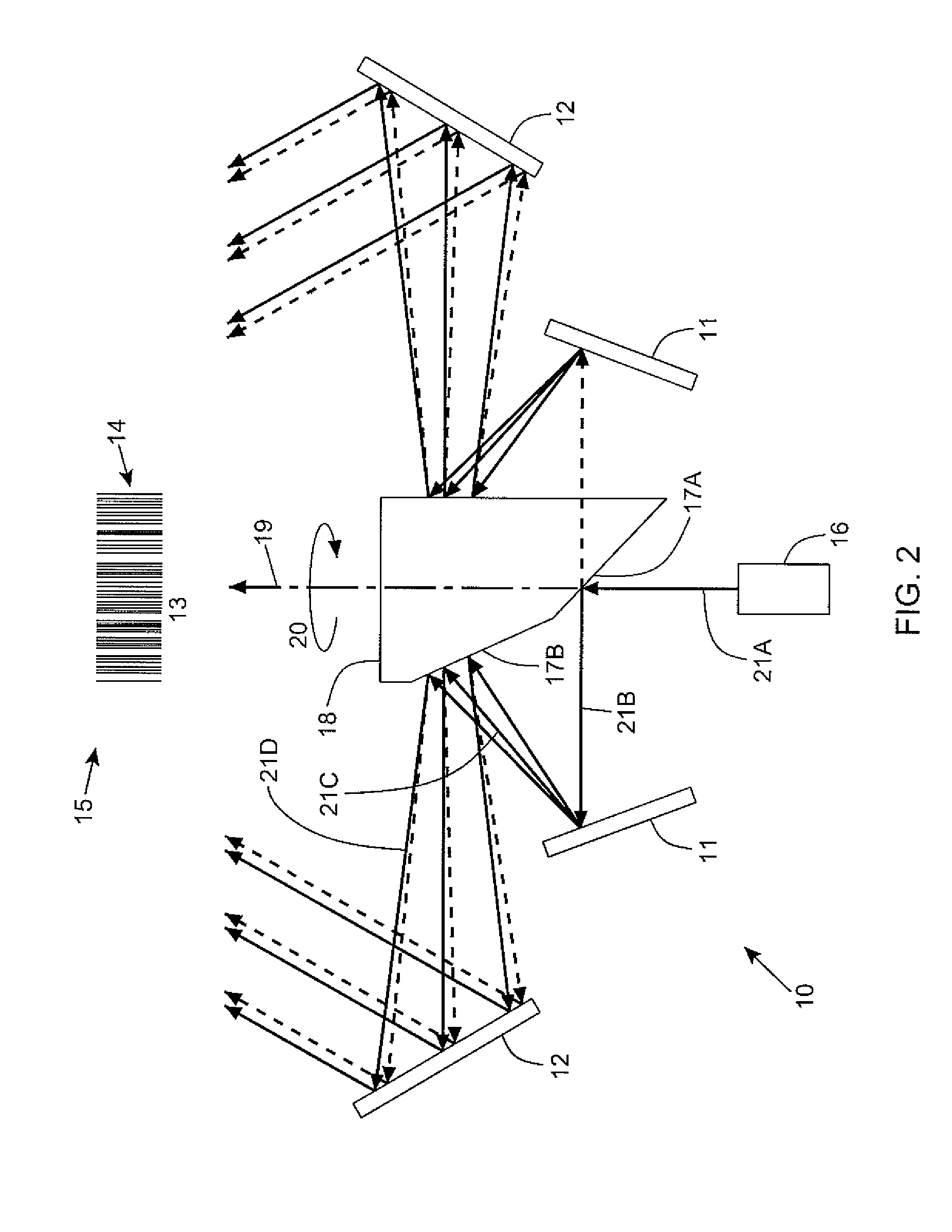
First Laser Scanning System Employing the Laser Scanning Assembly of the First Illustrative Embodiment

[0027]FIGS. 2 and 3 show the laser scanning assembly of the first illustrative embodiment 10 configured in combination with a first cluster of stationary mirrors 11, disposed within a seco...


PUM


Abstract

A laser scanning system for generating a laser scanning pattern in a scanning field, while amplifying the scan-angle multiplication factor of rotating mirrors employed therein. The laser scanning system employs rotatable laser scanning assembly having an axis of rotation and first and second rotating mirrors with normal vectors that are coplanar with each other and said rotational axis, and which form an acute angle substantially less than 90 degrees so as to provide a laser scanning assembly with a scan angle multiplication factor that is greater than 2.0. A cluster of stationary mirrors mounted about the first and second rotating mirrors, for sweeping a laser beam off the cluster of stationary mirrors after a laser beam has been reflected off the first rotating mirror, then reflected off the second rotating mirror, and then directed outwardly towards an array of pattern mirrors, so as to generate a resultant laser scanning pattern within the scanning field.

Description

BACKGROUND[0001]1. Field[0002]The present disclosure relates to optical scanning devices and more particularly to a new and improved laser scanning assembly having an improved angle multiplication factor.[0003]2. Brief Description of the State of the Art[0004]In many laser scanning bar code symbol readers, employing multi-line laser scanning patterns, a faceted mirror with a set number of sides facing generally different directions (i.e. a polygon) is used as the scanning element.[0005]However, a disadvantage of the polygon scanning element employed in such prior art scanning systems is that the achievable sweeping scan angle of a laser beam reflected off of such a scanning polygon can be no greater than two times the angle of rotation, and is usually less than two times. Also, in order to approach the limiting factor of two, the incident laser beam as well as the normal vectors to the mirror surfaces must be nearly perpendicular to the rotation axis. This prevents the laser beam fr...

Claims


Application Information

Patent Timeline
Patent Type & Authority Patents(United States)
IPC IPC(8): G02B26/00
CPCG02B5/09G02B26/105G02B26/12G06K7/10613G06K7/10623G06K7/10693
Inventor GOOD, TIMOTHY
Owner METROLOGIC INSTR INC
Why Eureka
Try Eureka