Light weight electrochromic mirror stack

a technology of electrochromic mirrors and mirror stacks, applied in the field of electrochromic mirrors, can solve the problems of reducing the frequency of mirror vibration, affecting the appearance of the mirror, and affecting the appearance of the mirror, and achieve the effect of light weigh

Inactive Publication Date: 2013-04-09
SAINT GOBAIN PERFORMANCE PLASTICS CHAINEUX
View PDF10 Cites 6 Cited by
  • Summary
  • Abstract
  • Description
  • Claims
  • Application Information

AI Technical Summary

Benefits of technology

[0011]The object of the invention is therefore to provide a rear view mirror that does not suffer from the interference that leads to iridescence. Moreover, the inventive mirror is light in weight, can be produced on foil which allows for bending and gluing on a not flat surface. Furthermore, it is an object of the invention to provide a method to make such a mirror.
[0017]Alternatively, ternary compounds containing lithium can be used for the ion conductor such as lithium phosphate, lithium phosphorus oxynitride, lithium niobate, lithium silicate, lithium aluminum silicate, lithium silicon oxynitride, and lithium silicon phosphorus oxynitride, lithium aluminum fluoride, lithium nickel manganese oxide, lithium nickel cobalt manganese oxide, lithium nickel cobalt oxide, lithium vanadium oxide, lithium iron phosphate, lithium vanadium phosphate, lithium cobalt vanadium oxide, lithium titanium oxide, lithium silicon tin oxynitride. By adjusting the electrochromic electrode composition, it is possible to eliminate the separate charging step that otherwise would be needed (see further).
[0019]It should be noted that the electrochromic effect of one of the electrochromic electrodes does not have to be specifically in the visual region of the spectrum. Indeed, one of the electrochromic layers could act as an ion store for storing the ions that have been extracted from the opposite electrode with a negligible effect on the visual transparency. Transparent compounds which are known for this are for example vanadium oxide (V2O5) and titanium oxide (TiO2).

Problems solved by technology

Such an assembly is much lighter than the known assemblies wherein the layers are held between at least two glass panes, considerable adding to the weight of the mirror.
As a consequence, the higher weight results in a lower frequency of vibration of mirrors that causes a blurred rearview.
However, because the thicknesses of the layers in the electrochromic stack come close to the visible wavelength, the reflection at the different interfaces leads to interference of the light rays.
This results in a distorted colour of the reflected image that moreover depends on the angle under which the rays are reflected (sometimes called iridescence).
A too much distorted colour will lead to confusion for the driver and is not acceptable (see e.g. EU Directive 2003 / 97 / EC, section 3.5 of Annex 2).

Method used


Image

  • Light weight electrochromic mirror stack
  • Light weight electrochromic mirror stack
  • Light weight electrochromic mirror stack

Examples


Embodiment Construction

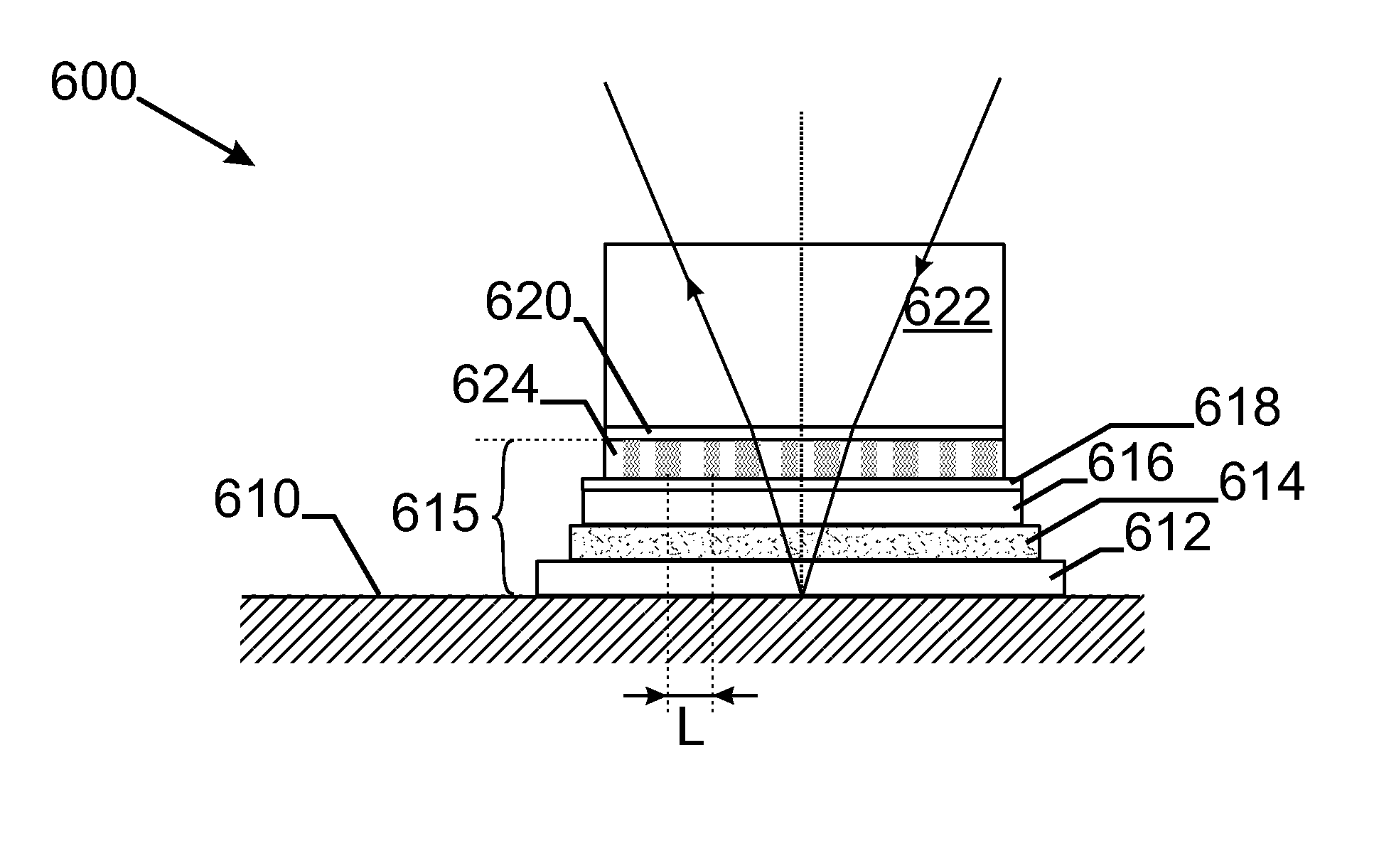
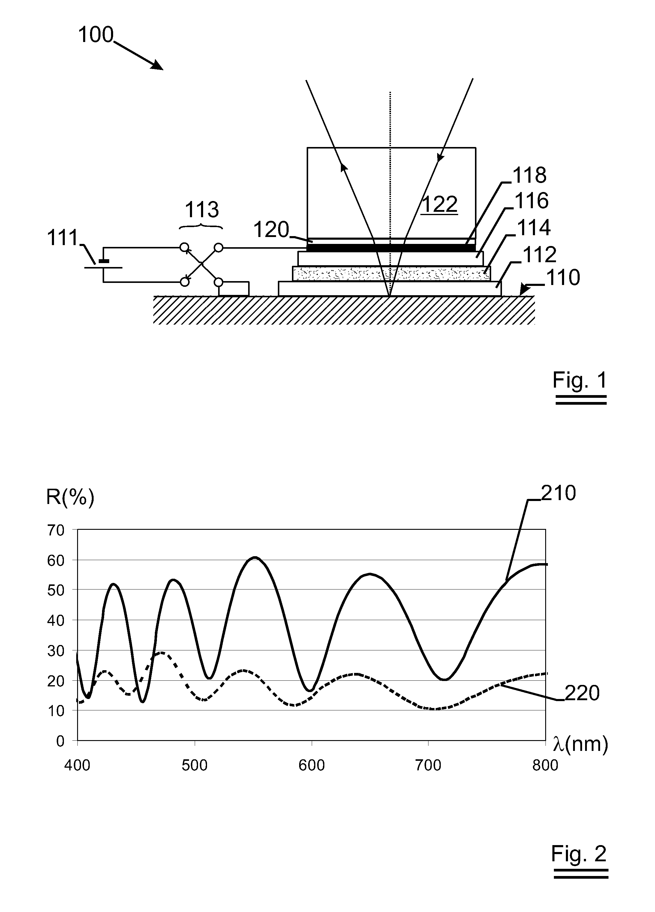
[0057]The prior-art device 100 as exemplary described in FIG. 1, consists of a reflective surface 110 that in this configuration acts as a first conductive layer on which a first electrochromic layer 112 is deposited, followed by an ion conductive layer 114 on which a second electrochromic layer 116 is laid down. The stack is finished with a transparent conductive layer 118. The mirror stack can be glued to a glass pane 122 by means of an adhesive layer 120 of e.g. PVB (polyvinyl butyral). An electric field responsive to the ambient light conditions is supplied through a DC voltage supply 111 can be interrupted or reversed through switch 113 in order to bring the device from a bleached into a darkened state and back.

[0058]The reflectogram of such a mirror stack is depicted in FIG. 2 wherein 220 denotes the reflective curve in the case of the darkened state and 210 the reflectance in case of the bleached state in range wherein the wavelength λ is scanned from 400 to 800 nm. Note that...


PUM

PropertyMeasurementUnit
reflectanceaaaaaaaaaa
wavelengthaaaaaaaaaa
diameteraaaaaaaaaa

Abstract

A light weight electrochromic dimmable mirror stack (300, 600) is presented that is composed only of solid-state layers (315, 615) with a total thickness of less than 50 micron and a reflector (310, 610). Normally such a kind of layered device suffers from iridescence due to interference of light waves reflecting at the interfaces between the layers of the electrochromic device. The solution provided by the invention is to pattern at least one of the layers (315, 615) in the device such that the interference effects are smeared out and a more neutral color is obtained. Various possible configurations are described and also the method to produce such a device.

Description

TECHNICAL FIELD[0001]The invention relates to the technical field of electrochromic mirrors used in applications such as rear view mirrors in vehicles.BACKGROUND ART[0002]The reflectivity of an electrochromic mirror device can be varied by applying a voltage over the device. This makes them ideal for use in rear view mirrors of vehicles. They solve the danger problem that the vehicle driver gets temporarily blinded after having looked into the reflected headlights of the vehicles trailing behind him. Already many different systems exist but the constant behind these electrochromic devices is that there occurs a change in transparency in a material layer due to the reduction or oxidation of an ionic species that is displaced under the action of an electric field. The ionic species can be a proton, or a lithium ion or—in rare cases—sodium or potassium ions.[0003]The existing systems differ in the kind of electrochromic layers that are used. The electrochromic layer is the layer that c...

Claims


Application Information

Patent Timeline
Patent Type & Authority Patents(United States)
IPC IPC(8): G02F1/153G02F1/1524
CPCB60R1/088G02F1/1523G02F1/157G02F1/1533G02F1/1524
Inventor WIDJAJA, EDYPERSOONE, PETER
Owner SAINT GOBAIN PERFORMANCE PLASTICS CHAINEUX
Why Eureka
Try Eureka