
System and method for dynamic multi-objective optimization of machine selection, integration and utilization

a multi-objective, dynamic technology, applied in adaptive control, process and machine control, instruments, etc., can solve the problems of not being optimal at the actual operating conditions, the cost of operating a pumping system is commonly of interest, and the system may seldom, if ever, be operated at these levels, so as to minimize the cost, optimize the cost, and minimize the cost per unit of fluid pumped

Active Publication Date: 2013-04-09
ROCKWELL AUTOMATION TECH
View PDF74 Cites 70 Cited by
  • Summary
  • Abstract
  • Description
  • Claims
  • Application Information

AI Technical Summary

Benefits of technology

This approach enhances efficiency, extends machinery life, reduces downtime, and improves overall business operations by optimizing performance characteristics such as energy usage, cost, and reliability, while aligning with high-level business objectives.

Problems solved by technology

However, the system may seldom, if ever, be operated at these levels.
For instance, the cost of operating a pumping system is commonly of interest in a manufacturing facility employing the system.
. . ) for the components and / or the system of which they form a part, are not typically optimal at the actual operating conditions.
Thus, even where the efficiency ratings for a pump, motor, and motor drive in a motorized pumping system provide for maximum efficiency at or near the maximum flow rate specified for the pumping system, the efficiency of one or more of these components (e.g., as well as that of the pumping system overall) may be relatively poor for other flow rates at which the system may operate for the majority of the service life thereof.
Moreover, typically, the specification for such machines or components thereof is performed at an isolated or level of granularity such that higher-level aspects of a business or industrial concern are overlooked.

Method used


Image

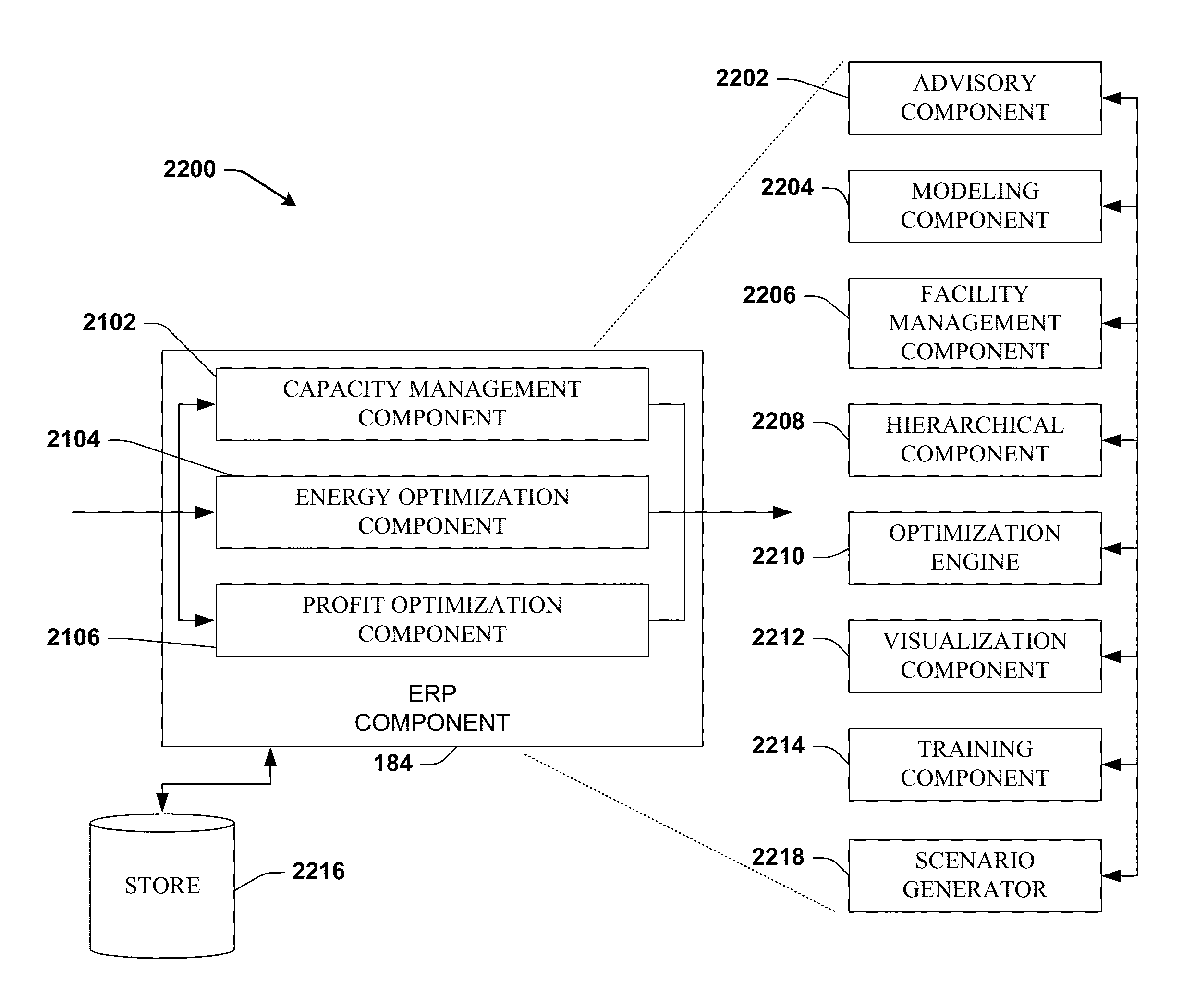
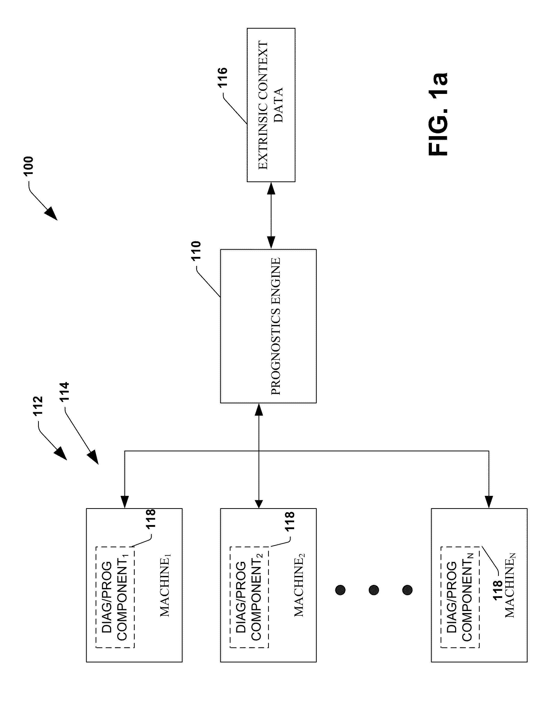
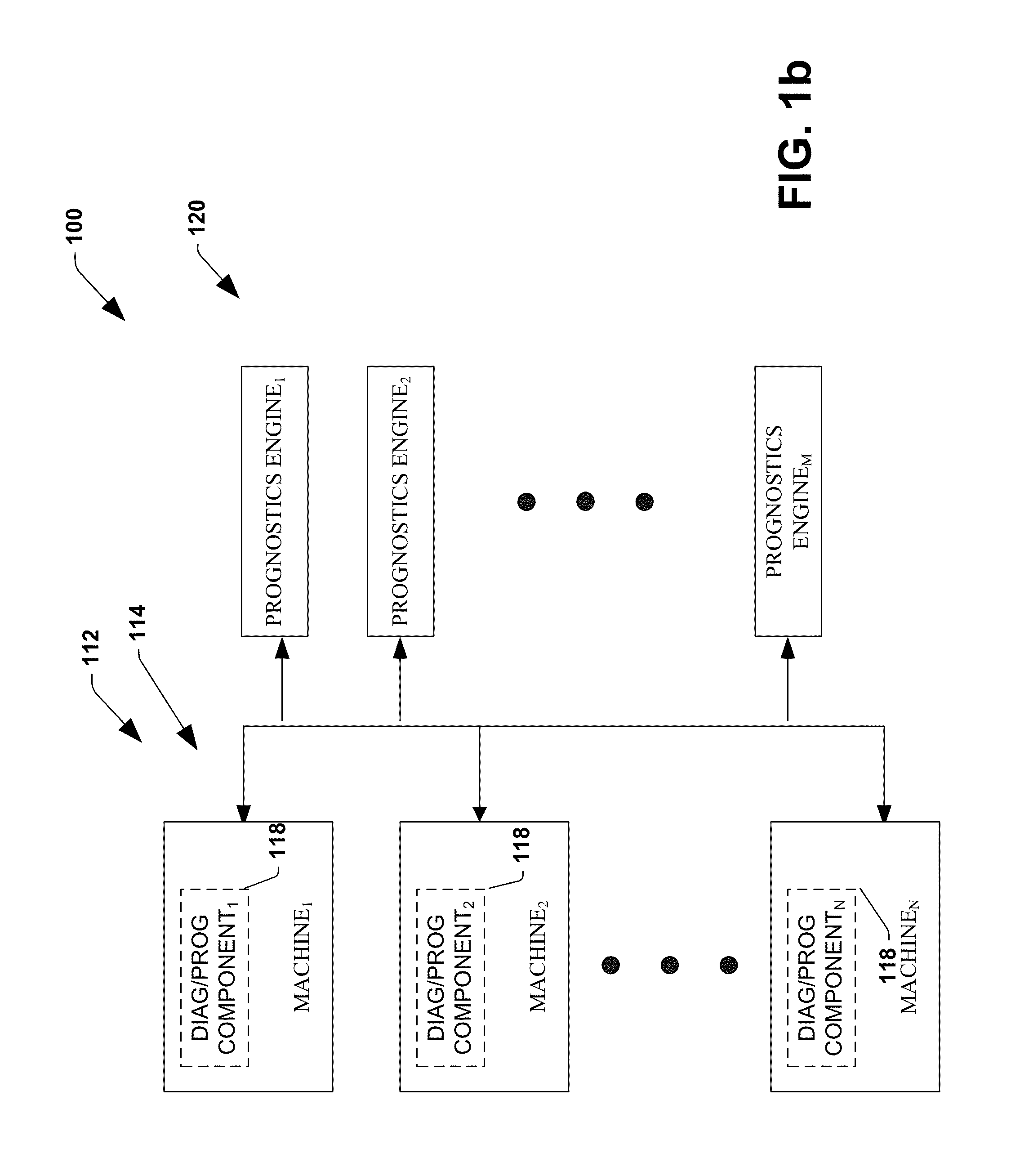
  • System and method for dynamic multi-objective optimization of machine selection, integration and utilization
  • System and method for dynamic multi-objective optimization of machine selection, integration and utilization
  • System and method for dynamic multi-objective optimization of machine selection, integration and utilization

Examples


Embodiment Construction

[0061]The present invention is now described with reference to the drawings, wherein like reference numerals are used to refer to like elements throughout. In the following description, for purposes of explanation, numerous specific details are set forth in order to provide a thorough understanding of the present invention. It may be evident, however, that the present invention may be practiced without these specific details. In other instances, well-known structures and devices are shown in block diagram form in order to facilitate describing the present invention.

[0062]As used in this application, the terms “component” and “system” are intended to refer to a computer-related entity, either hardware, a combination of hardware and software, software, or software in execution. For example, a component may be, but is not limited to being, a process running on a processor, a processor, an object, an executable, a thread of execution, a program, and / or a computer. By way of illustration...


PUM


Abstract

Systems and methodologies are provided for controlling a process having computer-controlled equipment, which provide for optimized process performance according to one or more performance criteria, such as efficiency, component life expectancy, safety, emissions, noise, vibration, operational cost, or the like. The systems and methods provide for employing machine diagnostic and / or prognostic information in connection with optimizing an overall business operation over a time horizon.

Description

CROSS REFERENCE TO RELATED APPLICATIONS[0001]This application is a continuation in part application of co-pending U.S. Ser. No. 10 / 674,966, entitled SYSTEM AND METHOD FOR DYNAMIC MULTI-OBJECTIVE OPTIMIZATION OF MACHINE SELECTION, INTEGRATION AND UTILIZATION, filed on Sep. 30, 2003, which is a continuation in part application of U.S. Ser. No. 10 / 214,927, entitled SYSTEM AND METHOD FOR DYNAMIC MULTI-OBJECTIVE OPTIMIZATION OF MACHINE SELECTION, INTEGRATION AND UTILIZATION, filed on Aug. 7, 2002, which claims the benefit of U.S. Provisional Patent Application Ser. No. 60 / 311,880, filed Aug. 13, 2001, entitled INTELLIGENT PUMPING SYSTEMS ENABLE NEW OPPORTUNITIES FOR ASSET MANAGEMENT AND ECONOMIC OPTIMIZATION, and U.S. Provisional Patent Application Ser. No. 60 / 311,596, filed Aug. 10, 2001, entitled INTELLIGENT PUMPING SYSTEMS ENABLE NEW OPPORTUNITIES FOR ASSET MANAGEMENT AND ECONOMIC OPTIMIZATION; the disclosures of which are hereby incorporated by reference as if fully set forth herein....

Claims


Application Information

Patent Timeline
Patent Type & Authority Patents(United States)
IPC IPC(8): G05B13/02
CPCG05B13/024G05B13/0265G05B13/0285G05B17/02G06Q10/04G06Q10/06H04L67/125Y02P90/82
Inventor SUSTAETA, ANGELLIN, KA-HINGSNYDER, RICTHERON, JOHN CHRISTOPHERFUNDERBURK, MARKSUGARS, MICHAEL EUGENEDISCENZO, FREDERICK M.BAIER, JOHN J.
Owner ROCKWELL AUTOMATION TECH
Learn More